background image

SERVICE MANUAL

Sony Corporation

Published by Sony Techno Create Corporation
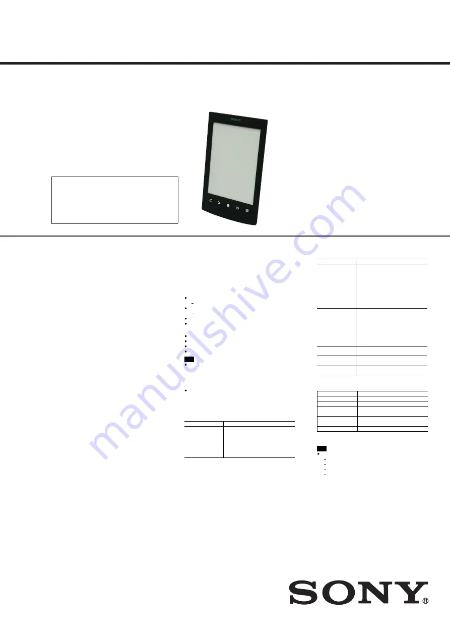
PRS-T2

SPECIFICATIONS

DIGITAL BOOK READER

9-893-536-01

2012H33-1

© 

2012.08

US Model

Canadian Model

AEP Model

UK Model

Australian Model

Ver. 1.0  2012.08

Note:

Be sure to keep your PC used for service and 
checking of this unit always updated with the 
latest version of your anti-virus software.
In case a virus affected unit was found during 
service, contact your Service Headquarters. 

Model name

PRS-T2

Power source

Built-in rechargeable battery: 3.7 V DC, 1000mAh
USB powered from a computer or the optional AC Adapter 
PRSA-AC10/PRSA-AC1A (sold separately) via the supplied 
USB cable.

Battery life (continuous page turn)

Maximum Battery: Approximately 30,000 continuous page 
turns when reading only.*
*  Measured using a text based content in ePub format and a 

fully charged battery, consecutive page-turns at 
approximately one second per page under the 
recommended operating temperature. Actual battery life 
may vary based on usage patterns and individual device.

Charging time

Computer-based charging: Approximately 2.5 hours
AC Adapter PRSA-AC10/PRSA-AC1A(sold separately)-based 
charging: Approximately 2 hours

Internal memory capacity (for data storage)

Approximately 1.3 GB after initial setting. 
Depending on size of pre-loaded excerpts, available memory 
capacity may vary.

Operating/Charging temperature

5°C to 35°C (41°F to 95°F)

Dimensions (w/h/d)

Approximately 110 × 173 × 9.1 mm (4 3/8 × 6 7/8 × 3/8 
inches)

Mass

Approximately 164 g (5.8 oz.)

Display

152.4 mm (6 inch) diagonal electrophoretic display 
600 × 800 pixels, 16-level grayscale

Wi-Fi

Wireless standards: IEEE 802.11b/g/n compliant
Wireless security: WEP (Open System), WEP (Shared Key), 
WPA-PSK (TKIP), WPA-PSK (AES), WPA2-PSK (TKIP), WPA2-PSK 
(AES)

Expansion slots

microSD card slot
See Details for supported card types and precautions.

Supplied items

USB cable × 1
Stylus × 1
Quick Start Guide

Supported File Types

The following files can be managed on the Reader software 
and transferred to the Reader device.
However, depending on the file size and format, it may not 
be possible to view/display/play some data.

Books

EPUB files (.epub)

EPUB (OPS version 2.0) supported.

PDF files (.pdf )

Support is based on the PDF 1.6 specification.

Text files (.txt)
FB2 files (.fb2)

Pictures

JPEG files (.jpg, .jpeg)
GIF files (.gif )
PNG files (.png)
BMP files (.bmp)

Note

If the size of a picture that you transferred with the Reader 
software is too large, a thumbnail may not be created on 
the Reader and the picture may not be displayed in the 
[Pictures] content list. In this case, delete the picture via the 
Reader software.
For an animated GIF file, only the first frame will be shown.

System Requirements

The Reader software will work with the following 
operating systems.

Operating System

Details

Microsoft Windows 
7 (32/64-bit)

Windows 7 Starter

Windows 7 Home Basic

Windows 7 Home Premium

Windows 7 Professional

Windows 7 Ultimate

Operating System

Details

Microsoft Windows 
Vista (32/64-bit)

Windows Vista Home Basic with 
Service Pack 2 or later

Windows Vista Home Premium with 
Service Pack 2 or later

Windows Vista Business with Service 
Pack 2 or later

Windows Vista Ultimate with Service 
Pack 2 or later

Microsoft Windows 
XP (32-bit only)

Windows XP Home Edition with 
Service Pack 3 or later

Windows XP Professional with Service 
Pack 3 or later

Windows XP Media Center Edition 
2004 & 2005 with Service Pack 3 or 
later

Mac OS X 10.7 (64-
bit only)

Mac OS X version 10.7 or later

Mac OS X 10.6 
(32/64-bit)

Mac OS X version 10.6.6

Mac OS X 10.5 (32-
bit only)

Mac OS X version 10.5.8

The Reader software also requires at minimum the 
following computing environment.

Requirement

Details

CPU

1 GHz Intel processor

RAM

512 MB

Free space on hard 
disc

250 MB or more*

Screen

1,024 x 768 display resolution with 
24-bit color

Network

Broadband internet connection

* Depending on the content amount, more space may be 

required.

Note

The Reader software is not supported with the following:

An operating system other than those listed above

A personally built computer or operating system
A multi-boot environment
A multi-monitor environment

Summary of Contents for Reader PRS-T2

Page 1: ... the Reader software and transferred to the Reader device However depending on the file size and format it may not be possible to view display play some data Books EPUB files epub EPUB OPS version 2 0 supported PDF files pdf Support is based on the PDF 1 6 specification Text files txt FB2 files fb2 Pictures JPEG files jpg jpeg GIF files gif PNG files png BMP files bmp Note If the size of a picture...

Page 2: ...d other countries This PRS T2 contains Adobe Reader Mobile software under license from Adobe Systems Incorporated Copyright 1995 2011 Adobe Systems Incorporated All rights reserved Adobe and Reader are trademarks of Adobe Systems Incorporated This product includes software developed by the OpenSSL Project for use in the OpenSSL Toolkit http www openssl org Copyright 1998 2011 The OpenSSL Project A...

Page 3: ...A Please do the following work when you exchange WLAN AN TENNA Manually setting a Wi Fi connection You can set up a Wi Fi network connection manually by inputting the required information for connection Make sure to turn on Wi Fi and tap Wi Fi Settings on the Wireless Network Settings screen Alternatively you can turn on Wi Fi by tapping the status bar and tapping Wi Fi Settings 1 Tap Add Wi Fi Ne...

Page 4: ...n be disassembled in the order shown below 2 1 DISASSEMBLY FLOW SET 2 2 REAR CASE BLOCK Page 5 2 3 MAIN BOARD Page 6 2 4 CASE FRONT ASSY Page 7 2 5 BATTERY ASSY BAT1 Page 8 2 6 LIGHT GUIDE ASSY LG1 Page 8 2 7 JACK BOARD CHASSIS ASSY EII1 Page 9 ...

Page 5: ... case block 9 rear case block Rear bottom side view 5 Insert the jig in the gap between rear case block and case front assy Then slide it to arrow direction to remove claws of rear case block Left side rear case block case front assy Right side rear case block case front assy 3 Insert the jig in the gap between rear case block and case front assy Then slide it to arrow direction to remove claws of...

Page 6: ...haft M1 4 u L1 6 8 screw M1 4 u L2 8 screw M1 4 u L2 8 screw M1 4 u L2 8 screw M1 4 u L2 8 two screws M1 4 u L2 8 screw M1 4 u L2 8 screw M1 4 u L2 8 screw M1 4 u L2 8 screw M1 4 u L2 Note 1 Please spread a sheet under a unit not to injure case front Note 2 WLAN antenna wire must not run aground to a boss 4 Remove three solders of battery wire Note 3 When soldering refer to ABOUT THE LEAD WIRE OF ...

Page 7: ...e six claws in order of the arrow C 8 case front assy 3 three tapping screws P2 3 tapping screw P2 3 two tapping screws P2 1 sheet AL 2 WLAN antenna connector MAIN board WLAN antenna ANT1 WLAN antenna wire WLAN antenna wire setting Note 1 Please spread a sheet under a unit not to injure case front Note 2 WLAN antenna wire must not run aground to a boss ditch sheet AL guide line ...

Page 8: ...ure case front 2 Remove three solders of battery wire Note 2 When soldering refer to ABOUT THE LEAD WIRE OF BATTERY ASSY BAT1 page 3 MAIN board Battery assy wire setting copper leaf PWB white red black battery assy BAT1 sheet cable Front bottom side view 3 light guide assy LG1 1 sheet switch flexible board 2 three shafts light guide 2 three shafts light guide ...

Page 9: ...dhesive sheet 4 3 6 adhesive sheet 4 3 2 claw 3 Pull out FPC M J5047 FPC1 from the slit slit 7 chassis assy EII1 4 FPC M J5047 FPC1 FPC M J5047 FPC1 convex part 5 JACK board JACK board Note When installing the FPC M J5047 FPC1 confirm the inserted direction 2 7 JACK BOARD CHASSIS ASSY EII1 ...

Page 10: ...nal Update Waveform IR LED Level Drawing with Points Update SP1 Parameters Check 3G Module TP Coordinate Check User History Test All Key Switch ADB Test Battery Life Fake MoAkey Version Confirmation Reboot Normal Check Battery Reboot Recovery Set Sleep Timeout Radio Logcat Get traces txt Factory Initialize Re fetch 3G Identifier Log Extact 2 Flush Reset Device Lock Power Off Log Extract 1 Check Te...

Page 11: ...tate of the factory shipment Procedure 1 Touch the Factory Initialize in the test mode menu Factory Initialize Would you like to execute Factory Initialize Yes No Screen display 2 When Yes is touched the deletion of all histories and reset of all settings are executed then this unit turn the power off 10 Update Waveform LUT rewriting and the LUT update confirmation can be executed As for ELEMENT I...

Page 12: ... lut bin file made in step 5 to the data folder made in step 10 12 Copy the file for the test mode from PC to directly under the READER drive of this unit Note 2 When the file for the test mode already exists directly under the READER drive of this unit the file for the test mode need not be newly copied 13 Remove this unit and USB cable MICRO B from PC 14 Enter the test mode Refer to HOW TO ENTER...

Page 13: ...C by the USB cable MICRO B 6 Confirm the USB connection screen displayed and touch the Yes Do you want the computer to recognize this device Tap Yes to install ReaderTM for PC or ReaderTM for MacR application or transfer content Tap No to use Reader while charging Note This screen will show whenever connecting with the USB cable OFF Yes No 7 The following screen is displayed in this unit and confi...

Page 14: ... display 13 Power Off This mode is not used in servicing 14 Log Extract 1 This mode is not used in servicing 15 Check Temperature This mode is not used in servicing 16 Write VCOM In this mode the VCOM voltage can be rewritten The VCOM voltage for ELEMENT INK INDICATOR 6inch is individually different Therefor when replacing the complete MAIN board or CHASSIS ASSY including ELEMENT INK INDICATOR 6in...

Page 15: ...act 1 Check Temperature Write VCOM WWAN ON WWAN OFF Write VCOM Status 1854mV Would you like to write New value 2030mV Yes No Example of displaying current unrenewed VCOM voltage 13 Touch the Yes it starts rewriting the VCOM voltage 14 Confirm the VCOM voltage has been updated Example 2030 mV in the figure below Test Mode Version X X X Target storage Internal Test Panal Update Waveform IR LED Level...

Page 16: ...6 4 435 250 41 CASE REAR BLACK RU 6 4 435 250 51 CASE REAR RED RU Ref No Part No Description Remark Ref No Part No Description Remark Note XX and X mean standardized parts so they may have some difference from the original one Items marked are not stocked since they are seldom required for routine ser vice Some delay should be anticipated when ordering these items The mechanical parts with no refe...

Page 17: ...ONT ASSY RED 55 4 408 115 01 SHEET 4X3 ADHESIVE ANT1 1 754 832 11 WLAN ANTENNA BAT1 A 1832 983 A BATTERY ASSY Ref No Part No Description Remark Ref No Part No Description Remark chassis section ANT1 A A 51 52 53 55 54 BAT1 52 55 Note 1 When soldering the battery assy BAT1 to the MAIN board refer to ABOUT THE LEAD WIRE OF BATTERY ASSY BAT1 page 3 Note 2 When replacing the WLAN antenna ANT1 refer to...

Page 18: ... 4 433 925 01 LEAF PWB COPPER 108 4 408 115 01 SHEET 4X3 ADHESIVE 109 4 438 998 01 COPPER SHEET2 EII1 A 1887 764 A CHASSIS ASSY Including ELEMENT INK INDICATOR 6 inch FPC1 1 884 637 11 FPC M J5047 LG1 A 1890 612 A LIGHT GUIDE ASSY Including SHHET SWITCH Ref No Part No Description Remark Ref No Part No Description Remark Note When replacing the MAIN board or CHASSIS ASSY EII1 refer to NOTE OF REPLA...

Page 19: ...GUIDE GERMAN DUTCH AEP UK AUS 4 435 720 31 QUICK START GUIDE SPANISH ITALIAN AEP UK AUS 4 435 720 41 QUICK START GUIDE DANISH FINNISH AEP UK AUS 4 435 720 51 QUICK START GUIDE NORWEGIAN SWEDISH AEP UK AUS 4 435 720 71 QUICK START GUIDE ENGLISH RUSSIAN RU 4 435 720 81 QUICK START GUIDE UKRAINIAN RU X 2582 530 1 STYLUS ASSY Stylus Abbreviation AUS Australian model CND Canadian model RU Russian model...

Page 20: ...HISTORY Checking the version allows you to jump to the revised page Also clicking the version at the top of the revised page allows you to jump to the next revised page Ver Date Description of Revision 1 0 2012 08 New ...

Reviews: