Sony PXW-Z450, Operating Instructions Manual
The Sony PXW-Z450 is a professional 4K camcorder designed for versatile shooting in various production environments. With advanced features and exceptional image quality, this compact camera provides unparalleled performance. For a comprehensive understanding of its functions, you can easily download the user manual for free from our website, manualshive.com.
Share
Download


Reviews:
No comments
Related manuals for PXW-Z450

GoXtreme race
Brand: Easypix Pages: 21

DVC 527
Brand: Easypix Pages: 13
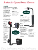
TiltTrigger Pro-SQ
Brand: Tiffen Pages: 1

DVR 430HD
Brand: Vivitar Pages: 37

Hi 8 SCL610
Brand: Samsung Pages: 71

DCS-5000L
Brand: D-Link Pages: 78

Palmcorder PV-DLT9
Brand: Panasonic Pages: 4

AW-PH405
Brand: Panasonic Pages: 2

AW-LZ14ST55
Brand: Panasonic Pages: 2

Palmcorder PV-LCD35
Brand: Panasonic Pages: 8

AWVF80P - ELECTRONIC VIEW FINDER
Brand: Panasonic Pages: 12

AWVF64N - 4" VIEWFINDER
Brand: Panasonic Pages: 12

AWVF80 - VIEWFINDER
Brand: Panasonic Pages: 12

AW-PB605P
Brand: Panasonic Pages: 16

BT-LT80W
Brand: Panasonic Pages: 20

DXG-590V HD
Brand: DXG Pages: 80

DS-2CC102P(N)-IRT
Brand: HIKVISION Pages: 21

ETX
Brand: Meade Pages: 2


