Sony PCS-1600, Operating Instructions Manual
The Sony PCS-1600 is a cutting-edge communication system that allows seamless connectivity. Unlock the full potential of this device with the Operating Instructions Manual available for free download at manualshive.com. This comprehensive manual provides valuable insights and step-by-step instructions for maximizing your experience with the Sony PCS-1600.
Share
Download


Reviews:
No comments
Related manuals for PCS-1600

CNC 8070
Brand: Fagor Pages: 10

CNC 8060
Brand: Fagor Pages: 172

CNC 8060
Brand: Fagor Pages: 112

MVC Series
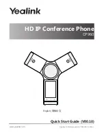
Brand: Yealink Pages: 6

MeetingSpace VC800
Brand: Yealink Pages: 6

MeetingEye 400
Brand: Yealink Pages: 16
One Talk CP960
Brand: Yealink Pages: 4
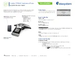
One Talk CP960
Brand: Yealink Pages: 20

VC400
Brand: Yealink Pages: 299

VC210 Teams Edition
Brand: Yealink Pages: 12
CP860 SERIES
Brand: Yealink Pages: 5

VC400
Brand: Yealink Pages: 16

MeetingBar A20
Brand: Yealink Pages: 30

MeetingSpace VC200
Brand: Yealink Pages: 8

MVC Series: MVC800
Brand: Yealink Pages: 16
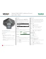
CP930W Telesystem
Brand: Yealink Pages: 2

VC110
Brand: Yealink Pages: 16

Fusion Z-7799
Brand: S.E.M. Pages: 6


