Sony IJ1001C, User Manual
The Sony IJ1001C User Manual is available for download, absolutely free, at manualshive.com. This comprehensive manual provides step-by-step instructions and valuable insights to help you make the most of your Sony IJ1001C product. Gain full control and optimize your experience with this must-have manual.
Share
Download


Reviews:
No comments
Related manuals for IJ1001C
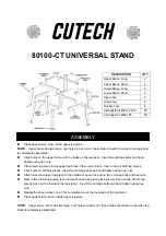
80100-CT
Brand: Cutech Pages: 2

DA7382
Brand: Dorel Asia Pages: 15

126060
Brand: Euromate Pages: 23

K7795
Brand: kincrome Pages: 3

03POH1010-V2
Brand: ManoMano Pages: 8

Fiberglass Underground Storage Tanks
Brand: Xerxes Pages: 31

HDD Box 250
Brand: Soyntec Pages: 8

6318280
Brand: Compaq Pages: 157

ESS-1KW
Brand: Sako Pages: 19

MS117000
Brand: Dancover Pages: 36

HDD-8263
Brand: National Instruments Pages: 20

sasbeast
Brand: Nexsan Pages: 6

DOUBLE BIN ULX-240-1
Brand: ulsonix Pages: 9

HA201-AP
Brand: AIC Pages: 64

NA762TB3
Brand: Netstor Pages: 17

TS-U100 - NAS Server - USB
Brand: TRENDnet Pages: 47

PRIMERGY SX910 S1
Brand: Fujitsu Pages: 46

PRIMERGY PG-DTA101
Brand: Fujitsu Pages: 70


