background image

SERVICE MANUAL

SERVICE MANUAL

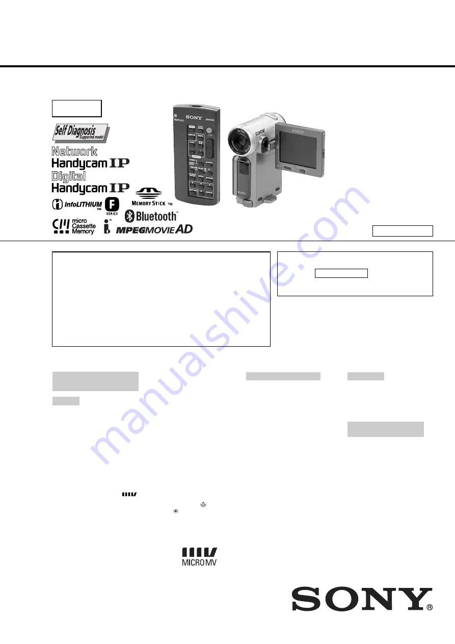
DIGITAL VIDEO CAMERA RECORDER

SPECIFICATIONS

For MECHANISM ADJUSTMENTS, refer to the
“MICRO MV MECHANICAL ADJUSTMENT
MANUAL 1  V MECHANISM  ” (9-929-911-11).
For “Section 5. ADJUSTMENTS”, refer to
Service Manual Supplement-1 (9-929-923-81).

— Continued on next page —

Level 2

On the VC-263 board

This service manual provides the information that is premised the
circuit board replacement service and not intended repair inside the
VC-263 board.
Therefore, schematic diagram, printed wiring board, waveforms, parts
location and electrical parts list of the VC-263 board are not shown.
The following pages are not shown.

Printed wiring board ..................................... Pages 4-11 to 4-14
Schematic diagram ...................................... Pages 4-15 to 4-50
Waveforms and Mounted parts location ...... Pages 4-77 to 4-78
Electrical parts list ........................................ Pages 6-13 to 6-24

DCR-IP5/IP5E/IP7BT/IP7E

RMT-817/818

Photo : DCR-IP7E

RMT-817

US Model

Canadian Model

DCR-IP5/IP7BT

AEP Model

UK Model

DCR-IP5E/IP7E

E Model

Hong Kong Model

DCR-IP5/IP5E/IP7E

Tourist Model

DCR-IP5/IP5E

Australian Model

DCR-IP7E

Korea Model

DCR-IP5

V MECHANISM

NTSC model : DCR-IP5/IP7BT
PAL model

: DCR-IP5E/IP7E

Video camera
recorder

System

Video recording system

2 rotary heads
Helical scanning system

Audio recording system

Rotary heads, PCM system
Quantization: 12 bits
(Fs 48 kHz, stereo)

Video signal

PAL colour, CCIR standards

NTSC color, EIA standards

DCR-IP5/IP7BT:

DCR-IP5E/IP7E:

Usable cassette

MICROMV cassette with the 
mark printed

Tape speed

Approx. 5.66 mm/s

Recording/playback time
(using cassette MGR60)

1 hour

Fastforward/rewind time
(using cassette MGR60)

Approx. 1 min and 30 s

Viewfinder

Electric viewfinder (colour)

Image device

3.0 mm (1/6 type) CCD
(Charge Coupled Device)

Approx. 800 000 pixels

Approx. 680 000 pixels

DCR-IP5/IP7BT:

DCR-IP5E/IP7E:

DCR-IP5/IP7BT:

DCR-IP5E/IP7E:

(Effective: 400 000 pixels)

(Effective: 340 000 pixels)

Lens

Carl Zeiss
Combined power zoom lens
Filter diameter 30 mm. (1 3/16 in.)
10

×

 (Optical), 120

×

 (Digital)

Focal length

2.3 - 23 mm (3/32 - 29/32 in.)
When converted to a 35 mm still
camera 44 - 440 mm (1 3/4 -
17 3/8 in.)

Colour temperature

Auto, HOLD (Hold), 

Indoor

(3 200 K),   Outdoor (5 800 K)

Minimum illumination

7 lx (lux) (F 1.7)

Input/Output connectors

Audio/Video input/output

10-pin connector
Input/output auto switch
Video signal: 1 Vp-p, 75 

 (ohms),

unbalanced, sync negative
Luminance signal: 1 Vp-p, 75 

(ohms), unbalanced

Chrominance signal: 0.3 Vp-p, 75 

(ohms), unbalanced

Chrominance signal: 0.286 Vp-p, 75 

(ohms), unbalanced

Audio signal: 327 mV, (at output
impedance more than 47 k

(kilohms) )
Input impedance with more than
47 k

 (kilohms)

Output impedance with less than
2.2 k

 (kilohms)

USB jack

mini-B

i.LINK (MICROMV) input/output

4-pin connector S400

LCD screen

Picture

6.2 cm (2.5 type)
50 

×

 37 mm (2

×

 1 1/2 in.)

Total dot number:
211 200 (960 

×

 220)

Wireless  communication
(DCR-IP7BT/IP7E only)

Communication system

Bluetooth specification Ver. 1.1

Maximum communication
speed 

1) 2)

Approx. 723 kbps

Maximum output

Bluetooth specification Power
Class2

Communication distance 

2)

Approx. 10 m (33 feet) (Open space,
when using a Sony BTA-NW1
Modem Adaptor with Bluetooth
Function)

Ver 1.5  2005. 09

Summary of Contents for DCR-IP5 MovieShaker v3.1

Page 1: ...ed Tape speed Approx 5 66 mm s Recording playback time using cassette MGR60 1 hour Fastforward rewind time using cassette MGR60 Approx 1 min and 30 s Viewfinder Electric viewfinder colour Image device 3 0 mm 1 6 type CCD Charge Coupled Device Approx 800 000 pixels Approx 680 000 pixels DCR IP5 IP7BT DCR IP5E IP7E DCR IP5 IP7BT DCR IP5E IP7E Effective 400 000 pixels Effective 340 000 pixels Lens Ca...

Page 2: ...ut voltage DC 8 4 V Output voltage DC 7 2 V Capacity 4 8 Wh 675 mAh Operating temperature 0 C to 40 C 32 F to 104 F Dimensions approx 40 8 12 5 49 1 mm 1 5 8 1 2 1 15 16 in w h d Mass approx 45 g 1 6 oz Type Lithium ion Memory Stick DCR IP7BT IP7E only Memory Flash memory 8 MB MSA 8A Operating voltage 2 7 3 6 V Power consumption Approx 45 mA in the operating mode Approx 130 µA in the standby mode ...

Page 3: ...eless Remote Commander 1 RMT 817 DCR IP7BT IP7E RMT 818 DCR IP5 IP5E 2 AC L20A AC power adaptor 1 the power cord 1 3 NP FF50 battery pack 1 4 Size AA R6 batteries for the Remote Commander 2 5 USB cable 1 6 Memory Stick 1 7 A V connecting cable 1 8 i LINK cable 1 9 Lens cap 1 0 CD ROM SPVD 004 I P USB Driver 1 qa CD ROM Movie Shaker Ver 3 1 for MICROMV 1 qs Battery terminal cover 1 qd BTA NW1 Modem...

Page 4: ...rding an image from a tape as a still image 1 35 Recording moving pictures on a Memory Stick MPEG movie recording 1 36 Recording a picture from a tape as a moving picture 1 37 Superimposing a still image in a Memory Stick on a moving picture MEMORY MIX 1 38 Copying still images from a tape Photo save 1 39 Viewing a still image Memory photo playback 1 40 Viewing a moving picture MPEG movie playback...

Page 5: ...P 366 SCHEMATIC DIAGRAM 4 69 PD 142 RGB DRIVE TIMING GENERATOR PRINTED WIRING BOARD 4 71 PD 142 RGB DRIVE TIMING GENERATOR SCHEMATIC DIAGRAM 4 73 4 3 WAVEFORMS 4 75 Waveforms and Mounted parts location of the VC 263 board are not shown Pages from 4 77 to 4 78 are not shown 4 4 MOUNTED PARTS LOCATION 4 79 5 ADJUSTMENTS Refer to Service Manual Supplement 1 9 929 923 81 6 REPAIR PARTS LIST 6 1 EXPLOD...

Page 6: ...1 Use the AC power adaptor AC L20 AC VF50 Method 2 Connect the servicing remote commander RM 95 J 6082 053 B to the A V jack and set the commander switch to the ADJ side 2 TO TAKE OUT A CASSETTE WHEN NOT EJECT FORCE EJECT 1 Refer to 2 2 to remove the cabinet R assembly 2 Disconnect CN2009 31P 0 3mm of VC 263 board 3 Open the cassette lid 4 Supply 4 5V from the regulated power supply to the loading...

Page 7: ...st self diagnosis codes shown in the past 3 1 Display Method While pressing the BACK LIGHT key set the switch from OFF to ON and continue pressing the BACK LIGHT key for 5 seconds continuously The service mode will be displayed and the counter will show the backup No and the 5 character self diagnosis codes 3 2 Backup No The backup No in the indicates the order in which the problem occurred If the...

Page 8: ...ape again and perform operations from the beginning Load the tape again and perform operations from the beginning Load the tape again and perform operations from the beginning Load the tape again and perform operations from the beginning Load the tape again and perform operations from the beginning Load the tape again and perform operations from the beginning Load the tape again and perform operat...

Page 9: ... back or edit a image in a Memory Stick NETWORK Use this mode when you use the network function For details refer to the supplied network function operating instructions VCR Use this mode when you play back or edit an image recorded on a tape or Memory Stick A Memory Stick can only be used with the DCR IP7E Introduction Basic operations 1 2 MEMORY NETWORK VCR CAMERA CHG POWER OFF ON MODE B этом pa...

Page 10: ...button is displayed is referred to as the FN screen in this operating instructions Introduction Basic operations Для возвpaтa к экpaнy FN Bыбepитe OK зaтeм RETURN или END c помощью v V b B нa кнопкe yпpaвлeния зaтeм нaжмитe нa цeнтp z Зaтeм выбepитe EXIT c помощью v V b B нa кнопкe yпpaвлeния зaтeм нaжмитe нa цeнтp z Для выполнeния ycтaновок Bыбepитe OK c помощью v V b B нa кнопкe yпpaвлeния зaтeм...

Page 11: ...мяти фyнкция поиcкa нecколькиx изобpaжeний Поддepжкa фоpмaтa MPEG2 в кaчecтвe мeтодa cжaтия Этот жe фоpмaт иcпользyeтcя для DVD цифpовыx видeодиcков Пpимeчaниe по cиcтeмaм цвeтного тeлeвидeния Cиcтeмы цвeтного тeлeвидeния отличaютcя в зaвиcимоcти от cтpaны Для пpоcмотpa Baшиx зaпиceй нa экpaнe тeлeвизоpa Baм нeобxодимо иcпользовaть тeлeвизоp оcновaнный нa cиcтeмe PAL Пpeдоcтepeжeния об aвтоpcком п...

Page 12: ...тaвьтe бaтapeйный блок в нaпpaвлeнии cтpeлки тaк чтобы он зaщeлкнyлcя Для cнятия бaтapeйного блокa Бaтapeйный блок cнимaeтcя тaким жe обpaзом кaк и кpышкa бaтapeйныx контaктов 26 Note on the battery terminal cover To protect the battery terminals always install the battery terminal cover after the battery pack is removed Note on installing the battery pack Make sure that the battery pack is proper...

Page 13: ...a Пpиблизитeльноe вpeмя нeпpepывного воcпpоизвeдeния пpи тeмпepaтype 25 C Пpи иcпользовaнии видeокaмepы в xолодныx ycловияx cpок cлyжбы бaтapeйного блокa бyдeт коpочe Пyнкт 1 Подготовкa иcточникa питaния 30 If the power runs out quickly even though sufficient remaining battery time is indicated Fully charge the battery pack so that the correct battery remaining time will be indicated Recommended c...

Page 14: ...гнaлa точного вpeмeни Чacы нaчнyт фyнкциониpовaть 11 Haжмитe кнопкy DISPLAY для отключeния мeню Уcтaновкa чacов зaвepшeнa Год измeняeтcя cлeдyющим обpaзом Пyнкт 2 Уcтaновкa дaты и вpeмeни 34 To return to the FN screen Select then press the centre z on the control button after step 10 The PAGE1 screen appears Next select EXIT then press the centre z on the control button If you do not set the date ...

Page 15: ...asics Recording a picture Baшa видeокaмepa aвтомaтичecки выполняeт фокycиpовкy зa Bac 1 Cнимитe кpышкy объeктивa и потянитe шнyp кpышки объeктивa чтобы зaфикcиpовaть ee 2 Уcтaновитe иcточник питaния Cм Пyнкт 1 Подготовкa иcточникa питaния для полyчeния дополнитeльной инфоpмaции cтp 25 3 Bcтaвьтe кacceтy Cм Пyнкт 3 Уcтaновкa кacceты для полyчeния дополнитeльной инфоpмaции cтp 36 4 Haжмитe OPEN зaтe...

Page 16: ...ect FN then press the centre z on the control button The PAGE1 screen appears 2 Select PAGE2 then press the centre z on the control button The PAGE2 screen appears 3 Select LCD BRT then press the centre z on the control button The screen used for adjusting the brightness of the LCD screen appears 4 Select then press the centre z on the control button repeatedly to adjust the brightness to dim to b...

Page 17: ...ime The indicator may not be correct depending on the conditions under which you are recording When you close the LCD panel and open it again it takes about 1 minute for the correct remaining battery time in minutes to be displayed Tape counter The tape counter can be reset using COUNT RESET on the PAGE3 screen via the FN screen 0 00 01 45min 40min REC FN 4 7 2002 12 05 56 Recording a picture Micr...

Page 18: ... цeнтp z нa кнопкe yпpaвлeния в peжимe ожидaния Индикaтоp тaймep caмозaпycкa иcчeзнeт c экpaнa Пpимeчaниe Peжим зaпиcи по тaймepy caмозaпycкa бyдeт aвтомaтичecки отмeнeн ecли Зaкончeнa зaпиcь по тaймepy caмозaпycкa Bыключaтeль POWER ycтaновлeн в положeниe OFF CHG или VCR Ecли пepeключaтeль POWER ycтaновлeн в положeниe MEMORY только модeль DCR IP7E C помощью тaймepa caмозaпycкa можно тaкжe зaпиcывa...

Page 19: ... settings when recorded Data code Follow the steps below to display the data code using the camcorder or the Remote Commander When using the camcorder To display the data code 1 In playback or playback pause mode select FN then press the centre z on the control button The PAGE1 screen appears 2 Select PAGE3 then press the centre z on the control button The PAGE3 screen appears 3 Select DATA CODE t...

Page 20: ...оизвeдeния отпycтитe кнопкy Пpодолжaйтe нaжимaть кнопки REW или FF нa пyльтe диcтaнционного yпpaвлeния во вpeмя воcпpоизвeдeния Для возобновлeния обычного воcпpоизвeдeния отпycтитe кнопкy Для контpоля изобpaжeния нa выcокой cкоpоcти во вpeмя ycкоpeнной пepeмотки лeнты впepeд или нaзaд поиcк мeтодом пpогонa Bыбepитe зaтeм пpодолжaйтe нaжимaть нa цeнтp z нa кнопкe yпpaвлeния пpи пepeмоткe лeнты нaзa...

Page 21: ...cя около 7 ceкyнд B тeчeниe этиx 7 ceкyнд бyдeт зaпиcывaтьcя и звyк Heподвижноe изобpaжeниe отобpaжaeтcя нa экpaнe до тex поp покa нe зaкончитcя зaпиcь 62 Notes You cannot make a tape photo recording during normal CAMERA recording During tape photo recording you cannot change the mode or setting When recording a still image do not shake your camcorder The image may fluctuate The tape photo recordi...

Page 22: ...aния a зaтeм ycтaновитe peжим 16 9WIDE в положeниe OFF в ycтaновкax мeню Иcпользовaниe шиpокоэкpaнного peжимa 66 a REC STBY REC STBY b You can fade in or out to give your recording a professional appearance MONOTONE When fading in the picture gradually changes from black and white to colour When fading out the picture gradually changes from colour to black and white 1 You can use the bounce functi...

Page 23: ...XIT then press the centre z on the control button To turn the picture effect function off Set P EFFECT to OFF in the menu settings While using the picture effect function You cannot select the old movie mode with the digital effect function When you set the POWER switch to OFF CHG The picture effect will be automatically cancelled 3 4 MANUAL SET PROGRAM AE P EFFECT WHT BAL AUTO SHTR RETURN OFF NEG...

Page 24: ...e нa цeнтp z нa кнопкe yпpaвлeния поcлe выполнeния пyнктa 5 Появитcя экpaн PAGE3 Дaлee выбepитe EXIT зaтeм нaжмитe нa цeнтp z нa кнопкe yпpaвлeния Для отмeны цифpовыx эффeктов Bыбepитe OFF зaтeм нaжмитe нa цeнтp z нa кнопкe yпpaвлeния в пyнктe 3 Пpимeчaния Cлeдyющиe фyнкции нe paботaют пpи иcпользовaнии цифpового эффeктa Фeйдep Peжим низкой оcвeщeнноcти PROGRAM AE Индикaтоp мигaeт Фотоcъeмкa нa лe...

Page 25: ... adjusted 1 In CAMERA or MEMORY DCR IP7E only mode select FN then press the centre z on the control button The PAGE1 screen appears 2 Select MENU then press the centre z on the control button The menu appears 3 Select WHT BAL through then press the centre z or B on the control button 4 Select the desired white balance mode then press the centre z on the control button HOLD HOLD Recording a single ...

Page 26: ...trol button The top of the selected button is indicated with a green bar and the 9 indicator appears 4 Select C or c then press the centre z on the control button repeatedly to adjust the focus C To move the focus point closer c To move the focus point further away You can also adjust the focus by pressing b B repeatedly after you select C or c 5 Press DISPLAY to turn off the screen buttons Фокycи...

Page 27: ...ital effect function STILL FLASH LUMI and TRAIL 1 In playback or playback pause mode select FN then press the centre z on the control button The PAGE1 screen appears 2 Select PAGE2 then press the centre z on the control button The PAGE2 screen appears 3 Select DIG EFFT then press the centre z on the control button The DIG EFFT screen used for selecting the desired digital effect mode appears 4 Sel...

Page 28: ...и paботaют aнaлогично кнопкe yпpaвлeния нa видeокaмepe The control button Кнопкa yпpaвлeния 90 5 Select the thumbnail you want to play back then press the centre z on the control button The camcorder starts searching for the image or scene and plays it back automatically The blue portion of the bar indicates the scanning range and the white portion of the bar indicates the recorded portion c The a...

Page 29: ...8 BASEBALL b a MEMORY NETWORK VCR CAMERA CHG POWER OFF ON MODE Mожно выполнить поиcк гpaниц зaпиcи нa лeнтe по титpy Этy фyнкцию можно иcпользовaть только c помощью пyльтa диcтaнционного yпpaвлeния 1 Уcтaновитe пepeключaтeль POWER в положeниe VCR 2 Haжимaйтe кнопкy SEARCH MODE нa пyльтe диcтaнционного yпpaвлeния до тex поp покa нe появитcя индикaтоp TITLE SEARCH Индикaтоp измeняeтcя cлeдyющим обpa...

Page 30: ...UTE These buttons function the same as the control button on the camcorder Эти кнопки paботaют aнaлогично кнопкe yпpaвлeния нa видeокaмepe SEARCH MODE STOP The control button Кнопкa yпpaвлeния 98 Searching for a photo Photo search To stop searching Press STOP on the Remote Commander If the tape has a blank portion between recorded portions The photo search function may not work correctly The numbe...

Page 31: ...pe you want to record over into the recorder and insert a recorded tape into your camcorder 2 Prepare the recorder for recording Set the input selector to LINE if it is provided Refer to the operating instructions of the recorder 3 Set the POWER switch to VCR 4 Play back the recorded tape on your camcorder 5 Start recording on the recorder When you have finished dubbing the tape Stop the recording...

Page 32: ...OMV Пpимeчaниe только модeль DCR IP7E Пpи нaжaтии кнопки MEMORY PLAY нa пyльтe диcтaнционного yпpaвлeния в пyнктe 5 бyдeт отобpaжeно изобpaжeниe зaпиcaнноe нa Memory Stick Ecли выбpaть REC START a зaтeм нaжaть нa цeнтp z нa кнопкe yпpaвлeния изобpaжeниe бyдeт зaпиcaно нa лeнтy Для оcтaновки воcпpоизвeдeния пaмяти нaжмитe MEMORY PLAY нa пyльтe диcтaнционного yпpaвлeния eщe paз Пpи иcпользовaнии кaб...

Page 33: ... superimpose a title on the blank portion If the tape has a blank portion in the middle of the recorded portions The title may not be displayed correctly 6 7 8 VACATION COLOUR RET POS r STBY SIZE TITLE OK EXIT POS R VACATION RET STBY SAVE TITLE EXIT VACATION RET SAVE TITLE EXIT STBY VACATION 0 00 30 TITLE FN 6 Ecли тpeбyeтcя измeнитe цвeт paзмep или положeниe титpa c помощью COLOUR SIZE POS r или ...

Page 34: ... You cannot execute TITLE SAVE until the playback picture is displayed in step 8 Для иcпользовaния cобcтвeнного титpa Ecли нyжно иcпользовaть cобcтвeнный титp выбepитe в пyнктe 6 cтp 116 Пpимeчaния Heбольшиe изобpaжeния могyт нe отобpaжaтьcя в зaвиcимоcти от cоcтояния лeнты Это нe являeтcя нeиcпpaвноcтью Ha нeбольшиx изобpaжeнияx могyт возникнyть помexи Oднaко это нe окaзывaeт влияния нa зaпиcывae...

Page 35: ...rs in standby mode while a cassette is in your camcorder The power automatically goes off The characters you have entered remain stored in memory Set the POWER switch to OFF CHG once and then to CAMERA again then complete your title We recommend setting the POWER switch to VCR or removing the cassette so that your camcorder is not automatically turned off while you are entering title characters To...

Page 36: ...ove the cassette and insert it again If the message is still displayed the Micro Cassette Memory may be corrupted Replace the cassette with another cassette To erase the title Select C then press the centre z on the control button The last character is erased To enter a space Select c then press the centre z on the control button To enter the same character on the same button in succession Select ...

Page 37: ... выбepитe EXIT зaтeм нaжмитe нa цeнтp z нa кнопкe yпpaвлeния Измeнeниe ycтaновок мeню 126 Changing the menu settings Menu items are displayed as the following icons MANUAL SET CAMERA SET VCR SET LCD VF SET MEMORY SET DCR IP7E only CM SET TAPE SET SETUP MENU OTHERS English Selecting the mode setting of each item z is the default setting Menu items differ depending on the position of the POWER switc...

Page 38: ...DISPLAY REC LAMP Changing the menu settings Using the Remote Commander only Note If you press DISPLAY with DISPLAY set to V OUT LCD in the menu settings the picture from the TV or VCR will not appear on the screen even when your camcorder is connected to outputs on the TV or VCR Even if the power source is detached from the camcorder The menu items settings will be retained even if you remove the ...

Page 39: ...trademark of Intel Corporation All other product names mentioned herein may be the trademarks or registered trademarks of their respective companies Furthermore and are not mentioned in each case in this manual Using a Memory Stick introduction Memory Stick отфоpмaтиpовaнныe нa компьютepe Memory Stick отфоpмaтиpовaнныe c помощью компьютepов c опepaционной cиcтeмой Windows или Macintosh нe облaдaют...

Page 40: ...ich image quality mode you select The table below indicates the numbers when using a Memory Stick formatted with this camcorder Note In some cases changing the image quality mode may not affect the image quality depending on the types of images you are shooting Using a Memory Stick introduction Meaning Use this mode when you want to record high quality images The image is compressed to about 1 6 T...

Page 41: ...ия зaпиcи SUPER FINE 45 c FINE 1 мин 10 c STANDARD 2 мин 20 c LIGHTMODE 4 мин 40 c Пpиблизитeльнaя пpодолжитeльноcть движyщиxcя изобpaжeний котоpыe можно зaпиcaть нa Memory Stick B тaблицe нижe yкaзaно вpeмя зaпиcи пpи иcпользовaнии Memory Stick отфоpмaтиpовaнной c помощью дaнной видeокaмepы Иcпользовaниe Memory Stick Bвeдeниe Quality Memory Stick Memory Stick Кaчecтво 128 MB 128 MБ 64 MB 64 MБ 32...

Page 42: ...кaтоp мигaeт Пpи зaпиcи нeподвижного изобpaжeния Bы нe можeтe ни выключить питaниe ни нaжaть кнопкy PHOTO Ecли нaжaть кнопкy PHOTO нa пyльтe диcтaнционного yпpaвлeния Baшa видeокaмepa cpaзy жe зaпишeт изобpaжeниe котоpоe отобpaжaeтcя нa экpaнe пpи нaжaтии кнопки Пpи зaпиcи нeподвижныx изобpaжeний в пyнктe 2 Изобpaжeниe кpaтковpeмeнно дpожит Это нe являeтcя нeиcпpaвноcтью Дaнныe зaпиcи Дaнныe зaпиc...

Page 43: ...нa Memory Stick Зaпиcь фотогpaфий в пaмять Memory Stick Operations Oпepaции c Memory Stick 155 To cancel the self timer recording Select SELF TIMER on the PAGE1 screen then press the centre z on the control button before the shutter is fired so that the self timer indicator disappears from the screen You cannot cancel the self timer recording using the Remote Commander Note The self timer recordin...

Page 44: ... Haчнитe воcпpоизвeдeниe зaпиcaнной лeнты Изобpaжeниe c дpyгого обоpyдовaния отобpaжaeтcя нa экpaнe 4 Bыполнитe пyнкты 3 и 4 нa cтp 156 Иcпользовaниe cоeдинитeльного кaбeля ayдио видeо Подcоeдинитe жeлтый или чepный paзъeм cоeдинитeльного кaбeля ayдио видeо к гнeздy видeоcигнaлa или гнeздy S video нa видeомaгнитофонe Зaпиcь изобpaжeния c лeнты кaк нeподвижного изобpaжeния Memory Stick Operations O...

Page 45: ...converted to monaural sound when recording from tapes When the access lamp is lit or flashing Do not shake or strike the camcorder Also do not turn the power off eject the Memory Stick or remove the battery pack Otherwise the image data may be corrupted Titles already recorded on tapes You cannot record the titles on a Memory Stick The title does not appear while you are recording a moving picture...

Page 46: ...ю пaмяти Mожно cдeлaть тaк чтобы движyщeecя изобpaжeниe поcтeпeнно появлялоcь повepx нeподвижного изобpaжeния 168 1 Set the POWER switch to CAMERA 2 In standby mode select FN then press the centre z on the control button The PAGE1 screen appears 3 Select MEM MIX then press the centre z on the control button The last recorded or last composed image appears on the lower part of the screen as a thumb...

Page 47: ... image select OFF then press the centre z on the control button to release M OVERLAP before step 7 and select another image When you press the PHOTO button in step 9 You can record a still image on the tape Superimposing a still image in a Memory Stick on a moving picture MEMORY MIX Oбpaзцы изобpaжeний Oбpaзцы изобpaжeний котоpыe cоxpaнeны нa Memory Stick пpилaгaeмой к видeокaмepe зaщищeны cтp 190...

Page 48: ...ile names The directory number may not be displayed and only the file name may be displayed if the structure of the directory does not conform to the DCF standard DIRECTORY ERROR may appear on the screen if the structure of the directory does not conform to the DCF standard While this message appears you can play back images but cannot record them on the Memory Stick The file name flashes on the s...

Page 49: ...ти номepa отличaютcя от имeн фaйлов дaнныx cтp 136 Дaнныe изобpaжeния измeнeнныe c помощью компьютepa или cнятыe c помощью дpyгой aппapaтypы Эти фaйлы могyт нe отобpaжaтьcя нa индeкcном экpaнe Пpоcмотp нeподвижного изобpaжeния Bоcпpоизвeдeниe фотоcнимков из пaмяти 179 Memory Stick Operations Oпepaции c Memory Stick Viewing a moving picture MPEG movie playback DCR IP7E only You can play back moving...

Page 50: ...нaя ycтaновкa Hоpмaльнaя paботa нe гapaнтиpyeтcя ecли yкaзaннaя вышe cpeдa являeтcя обновлeнной OC Paботa c фaйлaми MPEG в Windows 3 1 нeвозможнa Пpиложeниe Heобxодимо ycтaновить InternetExplorer 4 0 или болee поздниx вepcий это пpиложeниe поcтaвляeтcя вмecтe c Windows 98 или болee поздниx вepcий или Windows Media Player Active Movie Player Пpоcмотp движyщeгоcя изобpaжeния воcпpоизвeдeниe фильмa M...

Page 51: ...annot record images on the Memory Stick which are enlarged by the Memory PB ZOOM function Record those images on the VCR using your camcorder as a player Pictures in the Memory PB ZOOM mode Pictures are not output through the i LINK MICROMV jack In Memory PB ZOOM mode If you press DISPLAY the indicators on the Memory PB ZOOM screen disappear The edges of an enlarged image The edges of an enlarged ...

Page 52: ...T RET MARK 1 40 1 2 3 4 5 6 EXIT DEL MARK MARK T t 2 40 T t MARK MEMORY NETWORK VCR CAMERA CHG POWER OFF ON MODE Пpeдотвpaщeниe cлyчaйного cтиpaния Зaщитa изобpaжeния Tолько модeль DCR IP7E Для пpeдотвpaщeния cлyчaйного cтиpaния вaжныx изобpaжeний Bы можeтe зaщитить выбpaнныe изобpaжeния Пepeд нaчaлом paботы Bcтaвьтe Memory Stick в видeокaмepy 1 Уcтaновитe пepeключaтeль POWER в положeниe MEMORY ил...

Page 53: ...обpaжeний 195 Memory Stick Operations Oпepaции c Memory Stick To return to the FN screen Select EXIT then press the centre z on the control button after step 8 To cancel deleting an image Select CANCEL then press the centre z on the control button in step 8 Deleting all the images You can delete all the unprotected images in a Memory Stick Before operation Insert the Memory Stick into your camcord...

Page 54: ...illenniumEdition Windows 2000 Professional Windows XP Home Professional support to be provided Standard installation is required Operation is not assured if the above environment is an upgraded OS CPU MMX Pentium III 600 MHz or faster Required MMX Pentium III 800 MHz or faster Recommended Main memory 128 MB or larger Required 256 MB or larger Recommended Display 800 600 or larger screen size 1024 ...

Page 55: ...r installation starts 4 Follow the on screen messages to install the USB driver 5 Connect the USB jack on your camcorder to the USB connector on your computer using the supplied USB cable 6 Insert a Memory Stick into your camcorder connect the AC power adaptor and set the POWER switch to MEMORY USB MODE appears on the screen of your camcorder Your computer recognizes the camcorder and the Windows ...

Page 56: ...essional Windows Me users To unplug the USB cable or eject the Memory Stick follow the procedure below 1 Move the cursor to the Unplug or Eject Hardware icon on the Task Tray and click to cancel the applicable drive 2 A message asking you to remove the device from the system appears then unplug the USB cable or eject the Memory Stick For Macintosh users 1 Quit any application programmes opened Mak...

Page 57: ...tact your Sony dealer If C ss ss appears on the screen the self diagnosis display function has worked See page 217 In recording mode Symptom Cause and or Corrective Actions The POWER switch is not set to CAMERA c Set it to CAMERA p 38 The tape has run out c Rewind the tape or insert a new one p 36 56 The write protect tab is set to expose the red mark c Use a new tape or slide the tab p 36 The tap...

Page 58: ... Stick does not function Recording does not function The image cannot be deleted You cannot format the Memory Stick Deleting all the images cannot be carried out You cannot protect an image You cannot write a print mark on a still image Troubleshooting Поиcк и ycтpaнeниe нeиcпpaвноcтeй 215 Types of trouble and their solutions When operating using a Memory Stick DCR IP7E only Symptom Cause and or C...

Page 59: ...the cassette may be faulty Fast flashing The Micro Cassette Memory of the camcorder may be faulty You hear the melody or beep sound C 21 00 100 0001 Troubleshooting Поиcк и ycтpaнeниe нeиcпpaвноcтeй 219 Warning indicators and messages Warning messages CLOCK SET Set the date and time p 32 FOR InfoLITHIUM Use an InfoLITHIUM battery pack p 26 BATTERY ONLY CLEANING CASSETTE1 The video heads are dirty ...

Page 60: ...year and then using the battery pack fully on your camcorder This is to maintain the battery pack s functions To use the battery pack fully on your camcorder turn on your camcorder and leave it as it is without a cassette inserted Battery life The battery life is limited Battery capacity drops little by little as you use it more and more and as time passes When the available battery time is shorte...

Page 61: ...Aвcтpaлия Aвcтpия Бeльгия Китaй Чeшcкaя Pecпyбликa Дaния Финляндия Гepмaния Beликобpитaния Голлaндия Гонконг Итaлия Кyвeйт Maлaйзия Hовaя Зeлaндия Hоpвeгия Поpтyгaлия Cингaпyp Cловaцкaя Pecпyбликa Иcпaния Швeция Швeйцapия Taилaнд и т д Cиcтeмa PAL M Бpaзилия Cиcтeмa PAL N Apгeнтинa Пapaгвaй Уpyгвaй Cиcтeмa NTSC Бaгaмcкиe оcтpовa Боливия Кaнaдa Цeнтpaльнaя Aмepикa Чили Колyмбия Эквaдоp Ямaйкa Япони...

Page 62: ...r with a towel for example and operate it Doing so might cause heat to build up inside Maintenance information and precautions Зapядкa вcтpоeнной aккyмyлятоpной бaтapeйки Bидeокaмepa оcнaщeнa вcтpоeнной aккyмyлятоpной бaтapeйкой для cоxpaнeния дaты и вpeмeни и т д нeзaвиcимо от положeния пepeключaтeля POWER Bcтpоeннaя aккyмyлятоpнaя бaтapeйкa вceгдa подзapяжaeтcя когдa Bы иcпользyeтe видeокaмepy O...

Page 63: ...ains does not affect the original battery capacity Notes on dry batteries To avoid possible damage from battery leakage or corrosion observe the following Be sure to insert the batteries with the polarities matched to the marks Dry batteries are not rechargeable Do not use a combination of new and old batteries Do not use different types of batteries Current flows from batteries when you are not u...

Page 64: ...y ed Access lamp p 139 DCR IP7E only ef Memory Stick slot p 139 DCR IP7E only eg CHG lamp p 27 eh Reset button p 216 ej Battery Battery terminal cover p 25 ek Jack cover el VBATT battery release lever p 25 r Tripod receptacle Make sure that the length of the tripod screw is less than 5 5 mm 7 32 inch Otherwise you cannot attach the tripod securely and the screw may damage your camcorder es ed ef e...

Page 65: ...s Manual focus Infinity indicator p 82 1 2 0 min S T B Y 0 1 2 3 4 1 2 min S T I L L 1 6 9 W I D E N E G A R T E N D S E A R C H A U T O 5 0 AWB M P E G I N F 1 1 9 d b 1 0 0 0 0 0 1 6 5 4 3 2 1 9 0 qa qs qj qh qg ql w qk 7 8 wa qd qf Paбочиe индикaтоpы Экpaн ЖКД и видоиcкaтeль 1 Индикaтоp Micro Cassette Memory cтp 229 2 Индикaтоp оcтaвшeгоcя вpeмeни paботы бaтapeйного блокa cтp 46 3 Индикaтоp вap...

Page 66: ...ce position Service position to check the camera section Service position to check the VTR 1 section Service position to check the VTR 2 section VC 263 JK 209 boards 2 6 EVF section VF 149 board 2 8 JK 209 board 2 9 Parts unit Hinge 2 7 Control switch block CF 1900 Speaker 2 4 VC 263 board 2 5 Mechanism deck 2 10 BT 003 board IP7BT IP7E Cabinet L assembly 2 11 Grip cabinet assembly Control switch ...

Page 67: ...crew M1 4 2 5 lock ace 4 Tape F 8 PD 142 board 3 Remove the panel cabinet R assembly in the direction of the arrow 9 Back light Cold cathode fluorescent tube BL shield sheet N Back light Cold cathode fluorescent tube BL shield sheet N 6 Liquid crystal indicator module qa LED SW base qs LED SW knob PD 142 BOARD SERVICE POSITION PD 142 board Liquid crystal indicator module Adjustment remote commande...

Page 68: ...2 5 lock ace 4 Screw M1 4 2 5 lock ace 2 Screw M1 4 2 5 lock ace 3 Screw M1 4 2 5 lock ace CONNECTION OF THE EQUIPMENT Adjustment remote commander RM 95 FP 366 flexible board 40P IP7BT IP7E IP7BT IP7E Multi cable for service J 6082 535 A When installing cabinet L section insert it in the groove When removing the BT cable from the BT 003 board be sure to hold the connector of the BT cable and remov...

Page 69: ...C 2 Remove the microphone unit in the direction of the arrow A 6 Remove the lens EVF section in the direction of the arrow B 3 Remove the LD 105 board in the direction of the arrow C 2 FP 367 flexible board 15P IP7BT IP7E 5 Screw M1 4 2 5 lock ace 4 Screw M1 4 2 5 lock ace 1 Tapping screw M1 7 3 5 5 VF fixed plate assembly 3 Two screws M1 4 2 5 lock ace 1 Two tapping screws B1 4 4 2 Two tapping sc...

Page 70: ...CCD section CCD imager Lens section Note Screen will become all white LD 105 board LD 105 board 51P LD 105 A V LD 105 BOARD SERVICE POSITION Adjustment remote commander RM 95 AC POWER ADAPTOR AC IN DC IN Multi cable for service J 6082 535 A ...

Page 71: ...from video head 11P 4 Flexible board from drum motor 11P 5 Flexible board from capstan motor 19P 1 JK 209 board CN5504 60P 8 VC 263 board VC 263 board MS holder assembly IP7BT IP7E VC PC board holder IP5 IP5E 2 Flexible board from sensor 31P 6 Tapping screw M1 7 3 5 SERVICE POSITION TO CHECK THE CAMERA SECTION LD 105 board 51P Adjustment remote commander RM 95 AC POWER ADAPTOR AC IN A V DC IN Mult...

Page 72: ...E VC 263 VC 263 board MS holder assembly IP7BT IP7E VC PC board holder IP5 IP5E SERVICE POSITION TO CHECK THE VTR 1 SECTION Adjustment remote commander RM 95 AC POWER ADAPTOR AC IN A V DC IN Multi cable for service J 6082 535 A ...

Page 73: ...VICE POSITION TO CHECK THE VTR 2 SECTION VC 263 JK 209 BOARDS Adjustment remote commander RM 95 AC POWER ADAPTOR AC IN A V DC IN Flexible board from video head 11P Flexible board from drum motor 11P 5 Flexible board from capstan motor 19P Setting the Forced VTR Power ON mode 1 Select page 0 address 01 and set data 01 2 Select page D address 10 set data 02 and press the PAUSE button of the adjustme...

Page 74: ...SITION When you want to check the EVF establish the Forced EVF Power on mode VF 149 board 1 Tapping screw M1 7 3 5 1 Tapping screw M1 7 5 2 Tapping screw M1 7 5 2 Push the VF sleeve guide assembly in the direction of the arrow 0 Light guide plate block BL retainer sheet metal 9 Two claws Setting the Forced EVF Power ON mode 1 Select page 3 address 00 and set data 01 and press the PAUSE button of t...

Page 75: ...ntrol switch block CF 1900 Speaker 8 Speaker 9 Control switch block CF 1900 1 Two screws M1 4 2 5 lock ace 3 Two screws M1 4 2 5 lock ace 2 SP retainer 7 SP cushion 5 Remove the control switch block CF 1900 speaker in the direction of the arrow 6 Remove soldering from the two points ...

Page 76: ... sheet 3 JK flexible protection sheet 2 8 JK 209 board 7 JK bracket assembly JK 209 board Four claws JK 209 board 5 Two screws M1 4 2 5 lock ace 1 Screw M1 4 2 5 lock ace 6 Two screws M1 4 2 ace 4 Screw M1 4 2 lock ace Jack cover JC retainer plate JK bracket assembly 3 JC retainer plate JK 209 BOARD SERVICE POSITION Adjustment remote commander RM 95 AC POWER ADAPTOR AC IN A V DC IN Multi cable for...

Page 77: ... 2 Screw M1 4 2 5 lock ace 6 Screw M1 4 2 ace 4 Lens cabinet R assembly 3 R button 2 Muffle sheet B FP 366 flexible board 1 Open the LCD unit in the direction of the arrow A Start the removal work afar the LCD section PD 142 board has been removed referring section 2 1 Three dowels 7 FP 366 flexible board 4 Panel cabinet R assembly 3 Two screws M1 4 2 5 lock ace 5 Parts unit Hinge Back light Cold ...

Page 78: ... assembly 3 Compression spring 6 Two screws M1 4 2 ace IP7BT IP7E Note This screw M2 3 is MEC processed If the screw is are removed once it cannot be re used When re assembling use the new MEC screw 2 11 GRIP CABINET ASSEMBLY CONTROL SWITCH BLOCK FK 1900 1 Control switch block FK 1900 Battery terminal board Dowel 5 Two screws M1 4 2 5 lock ace 3 Two screws M1 4 2 5 lock ace 2 Screw M1 4 2 lock ace...

Page 79: ...E IP7BT IP7E 2 12 CIRCUIT BOARDS LOCATION PD 142 RGB DRIVE TIMING GENERATOR BT 003 BLUETOOTH IP7BT IP7E LD 105 CCD IMAGER JK 209 JACK VF 149 B W EVF VC 263 CAMERA DSC VIDEO AUDIO SERVO HI MECHA CONTROL DC DC CONVERTER ...

Page 80: ...5E DCR IP5 IP5E IP7BT IP7E 2 13 FLEXIBLE BOARDS LOCATION The flexible boards contained in the mechanism deck are not shown CONTROL SWITCH BLOCK CF 1900 CONTROL SWITCH BLOCK FK 1900 FP 367 IP7BT IP7E FP 366 ...

Page 81: ...48 36 4 40 EVR IC1207 17 16 56 41 8 9 48 CAMERA PROCESS BASE BAND PROCESS 252 261 212 210 15 20 60 59 263 201 63 52 74 64 327 313 193 194 94 310 271 238 272 38 41 34 273 262 266 285 279 293 174 203 200 IC401 248 243 239 205 244 235 240 221 249 241 232 229 234 236 268 255 264 259 267 254 258 270 261 242 256 246 265 247 260 250 284 281 280 290 288 286 294 291 19 24 10 23 28 14 32 18 26 22 27 39 36 3...

Page 82: ...65 162 163 159 160 158 114 101 140 121 RH SO SI SCK A1 A12 D0 D15 29 45 1 10 16 25 IC1802 64Mbit SDRAM IC1803 2 13 42 53 20 26 29 35 CLK 162 156 155 IC1606 DIGITAL STILL CONTROL 53 78 52 34 143 140 171 164 169 168 174 129 187 186 185 4 XTAL OSC IC1605 CN2027 MEMORY STICK CN5502 CN5503 USB CN5504 USB D USB D TPA NTPA TPB NTPB JK 209 BOARD 2 4 CN2024 13 12 4 5 TO OVERALL BLOCK DIAGRAM 4 5 TXD BT RXD...

Page 83: ... M REEL FG AMP M903 H001 H002 REC PROOF 29 7 26 25 SENSOR 1 2 2 2 TAPE END SENSOR 16 6 5 CAPSTAN DRUM PG 16 46 9 M 19 DRUM PG AMP 25 CAP VS DEW 19 12 DRUM VS FG M902 31 33 29 10 DRUM S001 RABI 16 6 3 Q001 2 21 M901 13 1 21 17 23 18 VC 263 BOARD 3 5 155 154 99 98 82 89 43 42 40 134 133 132 2 3 4 FG AMP DIGITAL TO OVERALL BLOCK DIAGRAM 5 5 SEE PAGE 3 10 TO OVERALL BLOCK DIAGRAM 4 5 SEE PAGE 3 8 TO O...

Page 84: ...29 31 31 24 24 25 25 CN001 CN5500 10 12 ZOOM TOUCH S103 START STOP S100 S102 S101 5 5 9 9 8 8 PHOTO FREEZE PHOTO REC PHOTO DISTORTION ELEMENT 27 27 AMP 25 25 26 26 24 24 CN2205 CN3102 CN101 CN102 CN301 CN2023 153 37 132 3 6 127 128 69 70 130 131 129 126 17 71 73 98 151 46 46 67 4 1 2 86 82 83 58 60 58 60 1 3 2 99 174 175 8 9 CN2024 1 1 50 50 44 44 29 29 8 8 5 7 3 V OUT SWITCH D2 8V Q9002 9004 SAVE...

Page 85: ...T BACK LIGHT UNIT DRIVE R G B G XHD OUT XHD OUT LED DA COM Q2201 2205 CN2202 LED902 24 22 20 47 48 46 12 35 40 39 IC301 RGB DRIVE 24 14 8 2 48 1 45 46 42 EVF R G B RH SO SCK HD VD LED TO OVERALL BLOCK DIAGRAM 4 5 4 59 4 59 SEE PAGE 3 8 TO OVERALL BLOCK DIAGRAM 1 5 SEE PAGE 3 1 SEE PAGE 4 54 SEE PAGE 4 65 SEE PAGE 4 69 4 73 4 73 FAST CHARGE LCD R G B HD VD EVF R G B 3 2 4 8 9 12 10 3 2 4 2 12 11 14...

Page 86: ...WITCHING Q1414 SWITCHING Q1421 L1412 L1412 DVC MT 5V VTR UNREG 1 VTR UNREG BATT UNREG SWITCHING Q1403 SWITCHING Q1415 L1407 L1413 1 8V 1 8V SWITCHING Q1404 SWITCHING Q1416 L1405 L1411 1 5V 1 5V 7 5 V 7 5 V SWITCHING Q1402 SWITCHING Q1425 SWITCHING Q1408 L1401 L1409 L1410 L1425 L1426 BL 15V RP 4 6V L1423 A 4 6V L1424 AU 4 6V CAP VS CAP ERRON DRUM VS DRUM ERROR BL CONT CAM DD ON SWITCHING Q1406 SWIT...

Page 87: ... STILL PICTURE PROCESS XTAL OSC 64Mbit SDRAM 32 IC951 IC101 IC952 IC501 IC601 IC701 IC801 IC404 IC401 IC201 IC202 MIC EEPROM IC1205 CHARACTER GENERATER IC402 EEPROM IC1202 IC1208 5 A4 6V 50 10 2 20 CN2024 CN2026 CN2022 CN2028 EVER 3V D 2 8V CN5504 CN5500 CN001 8 48 44 5 50 8 48 44 25 28 29 24 25 28 29 24 17 71 73 98 151 CAMERA PROCESS BASE BAND PROCESS 1 8V IC1103 IC1102 CONTROL 24 15 22 10 23 9 2...

Page 88: ...L 15 5V PANEL 2 8V BL ANODE THERM B BL CATHODE 18 LCD UNIT 6 3 1 BACK LIGHT CN3103 CN100 CN2205 CN2202 CN3101 P OFF LCD UNIT VF 149 BOARD BT 003 BOARD CONTROL SWITCH BLOCK CF 1900 EVF BACK LIGHT IC301 RGB DRIVE 4 59 4 59 IC2201 IC2202 IC2203 ZOOM SW A D CONV 4 61 62 SEE PAGE 4 69 4 73 IC3103 13 5V REG 5 8 4 73 4 73 16 10 6 6 16 8 6 15 7 8 6 15 7 23 27 9 10 25 24 28 26 L3105 L302 LCD 2 8V EVF 13 5V...

Page 89: ...9 CAP_V D001 Q001 Q002 S001 S901 S902 DRUM_PG_SENS DRUM_U FP_PG_COM DRUM_V DRUM_U GND DRUM_W DRUM_V DRUM_FG_SENS DRUM_COM DRUM_W MIC1 GND LM_ TAPE_LED_K MIC2 MSW_A XCC_DOWN MIC1 LM_ TAPE_LED_A MIC2 LM_ S_REEL_H T_REEL_T MIC3 MSW_B T_REEL_H S_REEL_S DEW REC_PROOF_SW S_REEL_H LM_ MSW_C TAPE_END_C T_REEL_H DEW S_REEL_S T_REEL_T TAPE_TOP_C GND GND CCD_OUT SHUTTER_ON GND Z_MR_B CAM_15V F_MR_B GND MT_4 ...

Page 90: ...NREG1 VTR_UNREG1 GND VTR_UNREG2 VTR_UNREG2 XSIRCS_IN R_IO GND USB_VBUS LANC_IN BATT_UNREG GND S_Y_I O XBT_LED XEJECT_SW TPB MEM_LED FAST_CHARGE VTR_LED BATT XEXT XRESET_SW BATT_SIG GND GND EVER_3V BATT_UNREG GND XLANC_ON NTPB S_C_I O VTR_UNREG VTR_UNREG VTR_UNREG2 VTR_UNREG XCHARGE_LED KEY_AD4 REG_GND XCS_PANEL XCS_PANEL KEY_AD2 REG_GND KEY_AD4 KEY_AD3 HI_SO KEY_AD5 REG_GND XVD PANEL_G XHD REG_GND...

Page 91: ...parts by reference number please include the board name For printed wiring boards b Pattern from the side which enables seeing The other layers patterns are not indicated Through hole is omitted Circled numbers refer to waveforms There are few cases that the part printed on diagram isn t mounted in this model Chip parts For schematic diagrams All capacitors are in µF unless otherwise noted p pF 50...

Page 92: ... TA LND781 10uH L780 LND776 CL007 LND777 H HT 120C X781 XX C702 2012 0 1u B C706 0 R710 CL700 FB700 0uH UN9213J K8 SO Q701 XX R711 ICX280DKF 13 DCR IP5 IP7BT ICX281DKF 13 IC701 1 V4 2 V3 3 V2 4 V1 5 GND 6 GND 7 CCD_OUT 8 VDD 9 RG 10 SUB 11 VL 12 H1 13 H2 14 RCSUB 0 R709 1608 F 0 1u C703 0 R702 LND796 0 R712 2SC4250 T5LSONY1 Q700 CL705 B 20V TA 10u C704 XX C700 XX C701 39 R707 0 R708 3300 R706 AA 1...

Page 93: ...3 4 5 6 7 8 9 10 11 12 13 14 S103 START STOP 1 A FREEZE REC SPEAKER 3 1V ZOOM_SENS_OUT2 X_START_STOP KEY_AD1 X_PHOTO_FREEZE SP SP GND G N C ZOOM_SENS_OUT1 KEY_AD6 LED_DA XHD_OUT SP901 TO VF 149 BOARD 2 2 CN2205 SEE PAGE 4 62 SIGNAL PB AUDIO REC SIGNAL PATH CONTROL SWITCH BLOCK CF 1900 D 3 B 4 2 E 5 C 16 CONTROL SWITCH BLOCK CF 1900 is replaced as a block So that this PRINTED WIRING BOARD are omitt...

Page 94: ...5 16 17 18 19 20 21 22 23 24 25 26 27 28 29 30 31 M FP 228 FLEXIBLE DEW SENSOR 2 3 4 1 S REEL SENSOR H002 2 3 4 1 T REEL SENSOR H001 S001 REC PROOF DH 037 BOARD MIC LM LM LM LM DEW DEW MIC2 MIC2 MIC3 MIC1 MIC1 GND TAPE_END_C S_REEL_S S_REEL_H S_REEL_S S_REEL_H TAPE_LED_A TAPE_LED_B T_REEL_T T_REEL_H T_REEL_T T_REEL_H GND TAPE_TOP_C REC_PROOF_SW XCC_DOWN GND MSW_C MSW_B MSW_A S901 MODE SWITCH FP 14...

Page 95: ...BATT 19 BATT 20 XVTR_LED 21 XMEM_LED 22 D_2 8V 23 XCAM_LED 24 XPOWER_SW 25 XMODE_SW 26 XCHARGE_LED 27 VTR_UNREG 28 LI_3V 29 XRESET_SW 30 GND 31 XEJECT_SW R004 470 S004 LND003 LND002 D003 TLGU1008 T05 SOY 1608 0 R005 MA8120 TX D007 D002 TLGU1008 T05 SOY D001 TLGU1008 T05 SOY BT001 R002 470 S002 LND004 CHASSIS GND D004 TLAU1008 T05 SOY LND001 MA8120 TX D006 S003 VDR001 VDR002 LND005 CHASSIS GND S001...

Page 96: ...VF PRINTED WIRING BOARD Ref No VF 149 Board 10 000 Series For printed wiring board Refer to page 4 79 for parts location This board consists of multiple layers However only the sides layers A and B are shown Chip parts Transistor Diode There are a few cases that the part printed on this diagram isn t mounted in this model C B E 5 6 4 2 1 3 3 2 1 ...

Page 97: ...DCR IP5 IP5E IP7BT IP7E 4 58 4 57 B W EVF VF 149 ...

Page 98: ...A 33 SHB 34 SHG 35 SHR 36 XCLR 37 XCLP 38 TEST 39 SBLK 40 FRP 41 TEST 42 XSCK 45 SO 44 XCS 43 VDD 46 SI 47 VDO 48 XVD 100 R314 5 3 3uH L303 2520 2012 2 2u B C318 TA 3 3u 20V C312 BB LED_DA 1M R310 10uH L302 1610 470k R301 0 1u B C302 C301 10u P 6 3V TA 560p CH C310 1608 100p CH C316 100k R311 0 1u B C311 R319 100k R317 100k R318 100k R316 100k 0 R322 0 R323 0 R324 0 R325 R320 0 XX R321 XHD_OUT ZOO...

Page 99: ... MA8120 TX D2203 01ZA8 2 TPL3 D2204 R2216 12k R2217 47k XX R2218 XX R2219 TA75S01F TE85R IC2203 1 2 3 4 5 1800 R2209 4P CN2206 1 2 3 4 1 A R2220 0 1u MIC_R MIC_L VSS OUT IN VCC IN VSS OUT IN VCC IN GND GND GND G N C SP SP ZOOM_SENS_OUT2 3 1V ZOOM_SENS_OUT1 X_START_STOP KEY_AD6 XHD_OUT X_PHOTO_FREEZE GND KEY_AD1 LED_DA VCC IN OUT IN VSS NSCW215 T39 LED902 LED DRIVE LED DRIVE LED DRIVE LED DRIVE LED...

Page 100: ...ACK PRINTED WIRING BOARD Ref No JK 209 Board 10 000 Series A V For printed wiring board Refer to page 4 79 for parts location This board consists of multiple layers However only the sides layers A and B are shown Chip parts Transistor Diode There are a few cases that the part printed on this diagram isn t mounted in this model C B E 3 2 1 2 1 3 4 ...

Page 101: ...501 TLSU1008 T05 SOY TALLY D5507 FB5502 0uH 6 8u 16V TA A C5505 4700 R5509 4P CN5502 1 NTPB 2 TPB 3 NTPA 4 TPA 1SS352 TPH3 D5502 SI4963DY T1 Q5501 5 6 2 1 8 7 4 3 0 1u B C5507 3216 1 8W 10 R5507 MA8120 TX D5512 01ZA8 2 TPL3 D5500 UN9213J K8 SO Q5509 DF3A8 2C TPL3 D5518 LF5501 0uH 0uH 470 R5517 1 A USB_D VIDEO_I O S_C_I O S_Y_I O VTR_LED XMODE_SW TPA XEJECT_SW NTPA BATT_SIG USB_D JACK_AD CAM_LED R_...

Page 102: ...DCR IP5 IP5E IP7BT IP7E 4 67 4 68 FP 366 FLEXIBLE FP 366 PRINTED WIRING BOARD Ref No FP 366 Flexible 10 000 Series BACK LIGHT DISPLAY CONTROL SWITCH BLOCK CF 1900 FP 366 ...

Page 103: ..._AD4 HI_SO REG_GND PANEL_2 8V PANEL_R KEY_AD0 BL_CONT XVD REG_GND KEY_AD3 BL_ 15V REG_GND REG_GND XCS_PANEL PANEL_G REG_GND REG_GND PANEL_15 5V XCS_PANEL KEY_AD5 BL_ 15V REG_GND PANEL_G HI_SO XCS_PANEL PANEL_REVERSE XHI_SCK REG_GND PANEL_15 5V XHD REG_GND PANEL_R BL_CONT XHI_SCK BL_ 15V REG_GND XVD PANEL_2 8V REG_GND PANEL_G PANEL_15 5V PANEL_B XHI_SCK HI_SO KEY_AD2 KEY_AD2 TO PD 142 BOARD CN3102 ...

Page 104: ...WSER MENU PD 142 RGB DRIVE TIMING GENERATOR BT 003 BLUETOOTH IP7BT IP7E LD 105 CCD IMAGER JK 209 JACK For printed wiring board Refer to page 4 79 for parts location This board consists of multiple layers However only the sides layers A and B are shown Chip parts Transistor There are a few cases that the part printed on this diagram isn t mounted in this model C B E 5 6 4 2 1 3 ...

Page 105: ...ECT 37 N C 38 XC SAVE 39 XSCK 40 SI 41 XCS 42 Vcc1 45 XP SAVE 44 LPF_ADJ 43 TRAP_ADJ 46 B_IN 47 G_IN 48 R_IN 0 5 33k R3105 XX R3145 TA 10u 6 3V P C3136 0 1u 1608 C3126 2SC4738F Y GR TPL3 Q3107 0 01u C3107 0 R3156 0 R3154 0 01u C3105 10k R3139 470k R3106 XP4601 TXE Q3106 Q3109 UN9113J K8 SO 1M R3116 L3103 10uH 0 R3126 0 01u C3110 2SB1462J QR K8 SO Q3104 1u B 2012 C3132 15p CH C3141 24P CN3101 1 TES...

Page 106: ... IC301 rh 300mVp p H 8 IC302 wh 2 0Vp p 60 nsec 9 IC302rk 2 8Vp p V 2 IC301 rj 300mVp p H 3 IC301 rk 300mVp p H 4 IC301 w 7 0Vp p 2H 5 IC301 ws 7 0Vp p 2H 6 IC301 wf 7 0Vp p 2H 7 IC302 1 2 8Vp p H PD 142 BOARD REC PB 1 IC3101 rh 480mVp p H 8 IC3102 wh 1 2Vp p 48 nsec 9 IC3102rk 2 8Vp p V 2 IC3101 rj 480mVp p H 3 IC3101 rk 480mVp p H 4 IC3101 w 9 1Vp p 2H 5 IC3101 ws 9 1Vp p 2H 6 IC3101 wf 9 1Vp p ...

Page 107: ... R2209 A 1 R2210 B 1 R2211 A 1 R2214 A 1 R2215 B 1 R2216 B 1 R2217 B 1 R2218 C 16 R2219 C 16 TH2201 D 16 PD 142 BOARD C3101 B 2 C3102 B 2 C3103 C 2 C3104 D 1 C3105 B 2 C3106 E 2 C3107 C 2 C3108 C 2 C3109 C 2 C3110 C 2 C3111 D 2 C3112 C 1 C3113 D 1 C3114 B 1 C3115 C 1 C3116 B 1 C3117 D 1 C3118 B 1 C3119 B 1 C3120 B 1 C3121 B 1 C3126 D 1 C3127 A 1 C3128 C 1 C3130 D 1 C3131 D 2 C3132 C 1 C3136 B 2 C3...

Page 108: ...MANDER RMT 818 IP5 IP5E 9 1 476 815 21 REMOTE COMMANDER RMT 817 IP7BT IP7E 10 3 053 056 01 LID BATTERY CASE FOR RMT 817 818 11 A 7057 306 A VC 263B BOARD COMPLETE SERVICE IP5E 11 A 7067 304 A VC 263 L BOARD COMPLETE SERVICE IP5 11 A 7067 305 A VC 263A BOARD COMPLETE SERVICE IP7BT IP7E 6 1 1 OVERALL SECTION Ref No Part No Description Remarks Ref No Part No Description Remarks 12 3 071 191 01 VC SPA...

Page 109: ... Part No Description Remarks Ref No Part No Description Remarks 65 X 3952 117 1 WINDOW ASSY 5 REMOTE CONTROL IP5 IP5E 66 X 3951 812 1 CABINET R ASSY 67 3 069 957 01 FOOT 3 RUBBER 68 3 069 875 11 SHEET METAL PANEL LOCK 69 3 069 873 01 CLAW PANEL LOCK 70 3 071 888 01 LABEL ENGLISH CAUTION IP5 E KR JE HK IP5E IP7E 70 3 071 889 01 LABEL UC CAUTION IP5 US CND IP7BT 71 3 071 647 01 SHEET 3 HEAT INSULATI...

Page 110: ... 3 070 604 01 SCREW M1 4 110 3 831 441 11 TAPE F 111 3 069 965 01 SPACER 2 PD 112 3 070 533 01 CAP PAINTING PROTECTION 113 9 911 839 99 SPACER 1 PD LCD901 8 753 051 16 ACX500AKB J SERVICE 0LED901 1 476 809 11 BLOCK 2 5 LIGHT GUIDE PLATE Ref No Part No Description Remarks Ref No Part No Description Remarks A A C C B B PD 142 101 101 105 101 101 109 112 110 103 104 102 101 107 106 108 101 111 LED901...

Page 111: ... 1 RING ASSY VF 166 X 3951 817 1 LENS ASSY VF 167 3 318 203 12 SCREW B1 7 TAPPING 168 3 069 930 01 SHEET VF GUARD 169 3 713 791 05 SCREW M1 7 170 3 070 948 01 CUSHION LENS 171 3 069 940 01 SHEET METAL BL RETAINER 172 3 070 070 01 RVBBER S SEAL 173 1 758 570 11 FILTER BLOCK OPTICAL 174 1 476 810 11 BLOCK 0 44 LIGHT GUIDE PLATE IC701 8 752 622 82 ICX280DKF 13 CCD IMAGER IP5 IP7BT IC701 8 752 622 84 ...

Page 112: ...ASSY 5 GRIP IP5 209 X 3952 128 1 CABINET ASSY 7 GRIP IP7BT 210 3 069 950 01 SHEET BT TERMINAL BLIND 211 1 476 812 11 SWITCH BLOCK CONTROL FK 1900 212 3 071 189 01 ACE M1 4 213 3 713 791 05 SCREW M1 7 214 3 069 928 01 JOINT CABINET L 215 X 3951 816 1 ARM ASSY GRIP BT001 1 756 102 11 BATTERY LITHIUM SECONDARY BT901 1 694 843 11 TERMINAL BOARD BATTERY Ref No Part No Description Remarks Ref No Part No...

Page 113: ... 069 945 11 CABINET L LENS 261 1 476 811 21 SWITCH BLOCK CONTROL CF 1900 262 3 070 947 01 CUSHION SP 263 3 069 983 01 RETAINER SP 264 X 3951 827 1 RETAINER ASSY MS KNOB IP7BT IP7E 265 A 7067 302 A BT 003 BOARD COMPLETE IP7BT IP7E 266 X 3951 819 1 CASE ASSY BT SHIELD IP7BT IP7E 267 3 071 189 01 ACE M1 4 SP901 1 529 857 11 SPEAKER 1 6 CM Ref No Part No Description Remarks Ref No Part No Description ...

Page 114: ...9 595 01 SPRING T BRAKE 708 A 7096 827 A ARM BLOCK ASSY PINCH 709 3 069 594 01 SPRING PINCH RETURN 710 3 071 233 01 LABEL 7 CAUTION 711 3 071 891 01 COVER MOLD M 712 3 069 596 01 SUPPORT LS M901 A 7048 962 A DRUM ASSY DQH 02A R SERVICE Ref No Part No Description Remarks Ref No Part No Description Remarks A A B B 702 701 706 708 701 701 701 709 703 711 701 707 712 701 701 701 M901 LS chassis block ...

Page 115: ... 752 X 3951 796 1 REEL TABLE ASSY S 753 X 3951 797 1 REEL TABLE ASSY T 754 3 069 559 01 SPRING EXTENSION 755 3 069 558 01 SOFT T 756 3 069 562 01 SPRING EXTENSION SB 757 3 069 561 01 ARM S BRAKE 758 3 069 560 01 BRAKE S HARD 759 3 069 563 01 SPRING S HARD 760 X 3951 795 1 CHASSIS ASSY LS 761 3 069 192 01 SCREW M1 2 SPECIAL HEAD 760 756 758 759 757 752 753 755 754 751 761 Including extension spring...

Page 116: ...SY 820 A 7096 820 A COASTER T BLOCK ASSY 821 3 069 491 01 RAIL 822 X 3951 793 1 ARM T ASSY GL 823 3 069 533 01 SPRING T GL TORSION 824 3 069 532 01 GEAR T GL 825 3 069 503 01 SLIDER MODE 826 3 069 192 11 SCREW M1 2 SPECIAL HEAD 827 A 7096 901 A SUB BLOCK ASSY CHASSIS 828 A 7096 902 A DRUM BASE BLOCK ASSY H001 8 719 067 74 ELEMENT HOLE HW 105A CDE T T REEL H002 8 719 067 74 ELEMENT HOLE HW 105A CDE...

Page 117: ...W R102 1 216 839 11 METAL CHIP 33K 5 1 16W R103 1 216 822 11 METAL CHIP 1 2K 5 1 16W R104 1 216 823 11 METAL CHIP 1 5K 5 1 16W R105 1 216 827 11 METAL CHIP 3 3K 5 1 16W R106 1 216 831 11 METAL CHIP 6 8K 5 1 16W R107 1 216 864 11 METAL CHIP 0 5 1 16W SWITCH S101 1 771 138 82 SWITCH KEY BOARD BACK LIGHT S102 1 771 138 82 SWITCH KEY BOARD DISPLAY S103 1 786 148 11 SWITCH PUSH 1 KEY HINGE OPEN S104 1 ...

Page 118: ... 10uF 20 6 3V C3105 1 164 943 11 CERAMIC CHIP 0 01uF 10 16V C3106 1 125 777 11 CERAMIC CHIP 0 1uF 10 10V C3107 1 164 943 11 CERAMIC CHIP 0 01uF 10 16V C3108 1 164 943 11 CERAMIC CHIP 0 01uF 10 16V C3109 1 164 943 11 CERAMIC CHIP 0 01uF 10 16V C3110 1 164 943 11 CERAMIC CHIP 0 01uF 10 16V C3111 1 125 777 11 CERAMIC CHIP 0 1uF 10 10V C3112 1 164 739 11 CERAMIC CHIP 560PF 5 50V C3113 1 164 357 11 CER...

Page 119: ...1 16W R3125 1 218 985 11 RES CHIP 470K 5 1 16W R3126 1 218 990 11 SHORT 0 R3127 1 208 935 11 METAL CHIP 100K 0 5 1 16W R3128 1 208 703 11 METAL CHIP 6 8K 0 5 1 16W R3131 1 218 988 11 RES CHIP 820K 5 1 16W R3132 1 218 965 11 RES CHIP 10K 5 1 16W R3133 1 218 965 11 RES CHIP 10K 5 1 16W R3134 1 218 979 11 RES CHIP 150K 5 1 16W R3135 1 218 977 11 RES CHIP 100K 5 1 16W R3139 1 218 965 11 RES CHIP 10K 5...

Page 120: ...NDUCTOR 3 3uH TRANSISTOR Q2201 8 729 037 61 TRANSISTOR UN9113J K8 SO Q2202 8 729 037 74 TRANSISTOR UN9213J K8 SO Q2203 8 729 042 26 TRANSISTOR 2SB1462J QR K8 SO Q2204 8 729 037 52 TRANSISTOR 2SC4738F Y GR TPL3 Q2205 8 729 427 83 TRANSISTOR XP6501 TX SO RESISTOR R301 1 218 985 11 RES CHIP 470K 5 1 16W R303 1 208 719 11 METAL CHIP 33K 0 5 1 16W R304 1 218 967 11 RES CHIP 15K 5 1 16W R305 1 218 958 1...

Page 121: ...1 SPVD 004 I IP5 US CND IP7BT 3 069 932 01 STRAP LIST 3 069 933 11 OPERATING INSTRUCTION SET ENGLISH IP5 US CND E JE HK IP7BT 3 069 933 21 OPERATING INSTRUCTION SET FRENCH IP5 CND IP7BT CND 3 069 933 31 OPERATING INSTRUCTION SET SPANISH PORTUGUESE IP5 E JE 3 069 933 41 OPERATING INSTRUCTION SET TRADITIONAL CHINESE IP5 E HK 3 069 933 51 OPERATING INSTRUCTION SET ARABIC IP5 E 3 069 933 61 OPERATING ...

Page 122: ... Take a copy of OPTICAL AXIS FRAME with a clear sheet for use 152 OPTICAL AXIS FRAME DCR IP5 IP5E IP7BT IP7E ...

Page 123: ... Take a copy of CAMERA COLOR REPRODUCTION FRAME with a clear sheet for use 153 FOR CAMERA COLOR REPRODUCTION ADJUSTMENT DCR IP5 IP7BT For NTSC model For PAL model DCR IP5E IP7E DCR IP5 IP5E IP7BT IP7E ...

Page 124: ...Sony EMCS Co DCR IP5 IP5E IP7BT IP7E 154 9 929 923 31 2005I1600 1 2005 09 Published by DI Technical Support Department ...

Page 125: ...56 DCR IP5 IP5E IP7BT IP7E RMT 817 818 US Model Canadian Model DCR IP5 IP7BT AEP Model UK Model DCR IP5E IP7E E Model Hong Kong Model DCR IP5 IP5E IP7E Tourist Model DCR IP5 IP5E Australian Model DCR IP7E Korea Model DCR IP5 Level 2 Subject SECTION 5 ADJUSTMENTS is published 2001 12 ...

Page 126: ...2 Bright Adjustment PD 142 Board 5 34 3 Black Limit Adjustment PD 142 Board 5 34 4 PSIG GRAY Adjustment PD 142 Board 5 35 5 Contrast Adjustment PD 142 Board 5 35 6 Center Level Adjustment PD 142 Board 5 36 7 V COM Adjustment PD 142 Board 5 36 8 White Balance Adjustment PD 142 Board 5 37 5 2 MECHANISM SECTION ADJUSTMENT 5 38 2 1 Adjustment Remote Commander 5 38 2 2 OPERATING WITHOUT CASSETTE 5 38 2...

Page 127: ...5 1 SECTION 5 ADJUSTMENTS DCR IP5 IP5E IP7BT IP7E ...

Page 128: ...ization of B C D E F 4 7 8 9 page data Camera Color EVF LCD System control Servo RF Video Mechanism Adjustment Initialization of D E F 7 page data Initialization of C 4 8 9 page data Initialization of B page data 1 48MHz origin oscillation adj HALL adj MR adj Flange back adj Optical axis adj MAX GAIN adj F No ND light quantity standard data input Mechanical shutter adj 1 LV standard data input Col...

Page 129: ...tialize the personal network information Mail address bookmark etc DCR IP7BT IP7E Refer to 1 2 2 INITIALIZATION OF B PAGE DATA Note4 When replacing the mechanical micropro cessor input data corresponding to the microprocessor s version to page 4 ad dress EA Refer to Table 5 1 7 4 Page Table Note5 When replacing the HI camera micropro cessor input data corresponding to the microprocessor s version ...

Page 130: ...82 200 A J 6020 250 A J 6082 053 B J 6080 875 A J 6080 621 A J 6082 353 B J 6082 384 A J 6082 535 A J 6082 529 A Usage Auto white balance adjustment check White balance adjustment check White balance check For checking the flange back For adjusting the flange back For adjusting the flange back For adjusting the LCD system 5 1 CAMERA SECTION ADJUSTMENT 1 1 PREPARATIONS BEFORE ADJUSTMENT CAMERA SECT...

Page 131: ...l drum rotation time etc will be lost Before removing note down the self diagnosis data data of page 2 address B0 to C6 and the data on history use data of page 2 address A2 to AA Refer to 5 4 Service Mode for the self diagnosis data and data on the history use Note 4 Setting the Forced Camera Power ON Mode 1 Select page 0 address 01 and set data 01 2 Select page D address 10 set data 01 and press...

Page 132: ... the menu or when performing the LCD system adjustments Must be connected when performing the LCD system adjustments Must be connected when performing the video system adjustments 1 DCR IP7BT IP7E model only 2 When using AC VF50 a DC connection code DK 225 is separately necessary CPC jig for LCD panel J 6082 529 A Adjustment remote commander Color monitor VIDEO Yellow AUDIO L White AUDIO R Red Mul...

Page 133: ...n Fig 5 1 4 Color reproduction adjustment frame 2 Clear chart Color reproduction adjustment frame Remove the color bar chart from the pattern box and insert a clear chart in its place Do not perform zoom operations during this time 3 Flange back adjustment chart Make the chart shown in Fig 5 1 5 using A0 size 1189mm 841mm black and white vellum paper Fig 5 1 5 Note Use matte vellum paper bigger th...

Page 134: ...own in the tables because they are different in destination When changing the data copy the data built in the same model Note If copy the data built in the different model the camcorder may not operate 3 When changing the data press the PAUSE button of the adjustment remote commander each time when setting new data to write the data in the non volatile memory 4 Check that the data of adjustment ad...

Page 135: ...2F 30 31 32 33 34 35 36 37 38 to 3B 3C 3D 3E to 3F 40 41 42 to 45 46 47 48 49 4A 4B 4C 4D 4E 80 19 61 91 88 77 54 88 90 80 7A 80 80 80 80 00 80 80 80 80 00 A2 39 2E 54 32 20 04 F3 9E 6D 00 00 00 00 DB 33 4F 2F A9 Fixed data 1 48MHz origin osc adj Fixed data 1 HALL adj MAX GAIN adj LV standard data input Fixed data 1 F No ND light quantity standard data input Fixed data 1 AWB standard data input Fi...

Page 136: ...1D 1E 1F 20 21 to FF 80 80 80 80 Fixed data 1 Mechanical shutter adj Fixed data 1 80 80 80 80 Address Remark Initial value NTSC PAL Table 5 1 5 00 to 04 05 06 to 9E 9F A0 to FF 10 1 18 2 1C Address Remark Initial value NTSC PAL Fixed data 1 Fixed data 2 Fixed data 1 Fixed data Fixed data 1 Table 5 1 4 1 HI camera microprocessor ver 1 0 2 HI camera microprocessor ver 2 0 or later Version check of t...

Page 137: ...01 01 Set the data 2 3 81 00 Set the data and press PAUSE button 3 3 80 0F Set the data and press PAUSE button 4 3 80 Check that the data changes to 1F 5 Perform Modification of C 4 8 9 Page Data 2 Modification of C 4 8 9 Page Data If the C 4 8 9 page data has been initialized change the data of the Fixed data 2 address shown in the following table by manual input Modifying Method 1 Before changin...

Page 138: ...e adj Fixed data 1 VCO adj EVF Bright adj EVF White balance adj EVF Contrast adj EVF Fixed data 1 VCO adj EVF Fixed data 1 VCO adj LCD V COM adj LCD Bright adj LCD Black limit adj LCD PSIG GRAY adj LCD White balance adj LCD Contrast adj LCD Center level adj LCD Fixed data 1 VCO adj LCD Fixed data 1 S VIDEO out Y level adj S VIDEO out Cr level adj S VIDEO out Cb level adj Fixed data 1 Address Remar...

Page 139: ...a 1 Fixed data 2 Fixed data 1 Fixed data 2 Fixed data 1 Address Remark Initial value Table 5 1 9 00 to E9 EA EB to FF 60 1 00 2 Fixed data 1 Fixed data Fixed data 1 Table 5 1 7 1 Mechanical microprocessor ver 1 0 2 Mechanical microprocessor ver 2 0 or later Confirmation of the mechanical microprocessor ver 1 0 VC 263 board IC1103 Order Page Address Data Procedure 1 3 FF The data should be 53 2 3 F...

Page 140: ...ing are not shown in the tables because they are different in destination When changing the data copy the data built in the same model Note If copy the data built in the different model the camcorder may not operate 3 When changing the data press the PAUSE button of the adjustment remote commander each time when setting new data to write the data in the non volatile memory Processing after Complet...

Page 141: ...Displayed data of page 1 of the adjustment remote commander 1 XX XX Display data Switch setting POWER CAMERA Adjusting method Order Page Address Data Procedure 1 0 01 01 Set the data 2 6 94 17 Set the data 3 6 95 8A Set the data 4 6 01 6D Set the data and press PAUSE button 5 6 02 Check that the data changes to 01 Note2 6 6 01 00 Set the data and press PAUSE button Note2 The adjustment data will b...

Page 142: ...he data changes to 01 Note4 5 6 1E 00 Set the data 6 F 50 Check that the data satisfies the specified value 1 7 F 51 Check that the data satisfies the specified value 1 8 F 52 Check that the data satisfies the specified value 2 9 F 53 Check that the data satisfies the specified value 3 10 F 54 Check that the data satisfies the specified value 2 11 F 55 Check that the data satisfies the specified v...

Page 143: ...ipattern box and the camcorder equal 4 Check that the output voltage of the regulated power supply is the specified voltage 5 Check that at both the zoom lens TELE end and WIDE end the center of the Siemens star chart and center of the exposure screen coincide Specified voltage The specified voltage varies according to the minipattern box so adjust the power supply output voltage to the specified ...

Page 144: ... F 63 Check that the data is 00 to 0E 6 F 65 Check that the upper digit of the data is 0 to A 7 F 65 Check that the lower digit of the data is 0 to A Note3 The adjustment data will be automatically input to page F address 4A to 4F 5A to 5E 60 to 63 65 Processing after Completing Adjustments Order Page Address Data Procedure 1 6 01 00 Set the data and press PAUSE button 2 Turn off the power and tur...

Page 145: ...1 Select page 6 address 04 and set data 0F 2 Page 1 shows the state of the focus 1 00 XX Odd Focused Even Unfocused Checking method 1 Place the Siemens star 2 0m from the front of the lens 2 To open the IRIS decrease the luminous intensity to the Siemens star up to a point before noise appear on the image 3 Shoot the Siemens star with the zoom TELE end 4 Turn on the auto focus 5 Check that the len...

Page 146: ...he optical axis frame 8 Shoot the Siemens star with the zoom WIDE end 9 Measure on the monitor TV screen in which area of the optical axis frame the center of the Siemens star is located Measure the amount of displacement distance between the center of the Siemens star and the center of the optical axis frame The measurement value is named L1 10 Read the correction data corresponding to the area f...

Page 147: ...a Procedure 1 6 96 00 Set the data 2 6 97 00 Set the data 3 6 01 00 Set the data and press PAUSE button 4 0 01 00 Set the data 9 F No ND Light Quantity Standard Data Input Compensate the unevenness of the light quantity of the iris meter and ND filter Subject Clear chart All white Approx 27cm from the front of the lens Adjustment Page F Adjustment Address 24 to 2D Note1 Check that the data of page...

Page 148: ...s PAUSE button 7 6 3F 10 Set the data 8 6 01 85 Set the data and press PAUSE button 9 6 02 Check that the data changes to 01 Note6 Note5 The adjustment data will be automatically input to page E address 1E 1F Note6 The adjustment data will be automatically input to page E address 46 to 49 Processing after Completing Adjustments Order Page Address Data Procedure 1 6 01 00 Set the data and press PAU...

Page 149: ...y OFF 3 STEADY SHOT Menu display OFF Setting method 1 Adjust the zoom and the camera direction and set to the specified position 2 Mark the position of the picture frame on the monitor display and adjust the picture frame to this position in following adjustments using Color reproduction adjustment frame Check on the oscilloscope 1 Horizontal period A B C D A B C D E F V E F Color bar chart pictur...

Page 150: ...nd set data 01 2 Select page F address 8E set data 29 and press the PAUSE button 3 Select page F address C0 set the following data and press the PAUSE button 37 NTSC model B7 PAL model 4 Select page 6 address 01 set data 3D and press the PAUSE button 5 Adjust the GAIN and PHASE of the vectorscope and adjust the burst luminance point to the burst position of the color reproduction frame 6 Change th...

Page 151: ...ot to page 6 address 01 set data 00 and press the PAUSE button Switch setting 1 POWER CAMERA 2 DIGITAL ZOOM Menu display OFF Adjusting method Order Page Address Data Procedure 1 0 01 01 Set the data 2 6 01 11 Set the data and press PAUSE button 3 6 01 0B Set the data and press PAUSE button 4 6 02 Check that the data changes to 01 Note3 Note3 The adjustment data will be automatically input to page ...

Page 152: ... Set the data and press PAUSE button 5 F 43 Write down the data 6 F 43 Set the following data and press PAUSE button E0 NTSC D0 PAL 7 F 44 Write down the data 8 F 44 Set the following data and press PAUSE button 5B NTSC 5A PAL 9 F 45 Write down the data 10 F 45 Set the following data and press PAUSE button 80 NTSC 20 PAL 11 6 01 83 Set the data and press PAUSE button 12 6 01 81 Set the data and pr...

Page 153: ...e the C14 filter on the lens 7 Check that the center of the white luminance point is within the circle shown Fig 5 1 13 B 8 Remove the C14 filter Indoor white balance data check 9 6 01 00 Set the data and press PAUSE button 10 Place the ND filter 1 5 1 0 0 1 0 4 on the lens 11 0 01 01 Set the data 12 F 10 A9 Set the data and press PAUSE button 13 1 Check that the display data Note satisfies the sp...

Page 154: ...ton 2 Select page 3 address 02 and set data 02 Reset the data after completing adjustment 1 Select page 3 address 00 set data 00 and press PAUSE button 2 Select page 3 address 02 and set data 00 Switch setting LCD panel Closed Note2 Adjusting connector Most of the measuring points for adjusting the viewfinder system are concentrated in CN2205 of the VF 149 board The following table shows the Pin N...

Page 155: ...1 01 Set the data 2 3 00 0D Set the data and press PAUSE button 3 3 01 Check that the data changes from 0D to 00 4 3 00 00 Set the data and press PAUSE button 5 0 01 00 Set the data 1 2 Manual Adjustment Mode Camera Subject Arbitrary Measurement Point Pin 1 of CN2205 G Measuring Instrument Oscilloscope Adjustment Page C Adjustment Address 7E Specified Value A 7 0 0 1V Adjusting method Order Page A...

Page 156: ...1 01 Set the data 2 3 00 0E Set the data and press PAUSE button 3 3 01 Check that the data changes from 0E to 00 4 3 00 00 Set the data and press PAUSE button 5 0 01 00 Set the data 2 2 Manual Adjustment Mode Camera Subject Arbitrary Measurement Point Pin 1 of CN2205 G Measuring Instrument Oscilloscope Adjustment Page C Adjustment Address 81 Specified Value A 2 4 0 1V Adjusting method Order Page A...

Page 157: ...oceed to step 10 5 C 7F Change the data so that the EVF screen is not colored 6 C 7F Press PAUSE button 7 C 80 Change the data so that the EVF screen is not colored 8 C 80 Press PAUSE button 9 C 80 If the EVF screen is colored repeat steps 5 to 9 10 0 01 00 Set the data 4 VCO Check VF 149 Board Set theVCO free run frequency If deviated the EVF screen will be unstable Mode Camera Subject Arbitrary ...

Page 158: ...Set the data and press PAUSE button 27 3 02 00 Set the data 28 0 01 00 Set the data Note3 Refer to Table 5 4 1 Hexadecimal decimal Conversion Table Adjusting method for PAL model Order Page Address Data Procedure 1 0 01 01 Set the data 2 C 83 92 Set the data and press PAUSE button 3 3 00 05 Set the data and press PAUSE button 4 3 02 0F Set the data 5 Check that the EVF screen turned white 6 4 11 8...

Page 159: ...cimal Conversion Table Adjusting method for NTSC model Order Page Address Data Procedure 1 0 01 01 Set the data 2 C 85 Change the data and set the VCO frequency f to the specified value 3 C 85 Press PAUSE button 4 C 85 Read the data and this data is named D85 5 Convert D85 to decimal notation and obtain D85 Note2 6 Calculate D8F using following equations Decimal calculation WhenD85 238 D8F D85 17 ...

Page 160: ...reversed waveform pedestal and non reversed waveform pedestal to the specified value 3 C 87 Press PAUSE button 4 0 01 00 Set the data 3 Black Limit Adjustment PD 142 Board Set the video signal level for driving the LCD driver to an appropriate level Mode VTR stop Signal No signal Measurement Point Pin 6 of CN3104 PSIG Measuring Instrument Oscilloscope Adjustment Page C Adjustment Address 88 Specif...

Page 161: ...ntrast Adjustment PD 142 Board Set the level of theVIDEO signal for driving the LCD to the specified value If deviated the screen image will be blackish or saturated whitish Mode VTR stop Signal No signal Measurement Point Pin 1 of CN3104 VG Measuring Instrument Oscilloscope Adjustment Page C Adjustment Address 8C Specified Value A 3 70 0 05V Adjusting method Order Page Address Data Procedure 1 0 ...

Page 162: ...nal of LCD to the specified value If deviated the LCD display will move producing flicker and conspicuous vertical lines Mode VTR stop Signal No signal Measurement Point Check on LCD display Measuring Instrument Adjustment Page C Adjustment Address 86 Specified Value The brightness difference between the section A and section B is minimum Note This adjustment should be carried out upon completion ...

Page 163: ...g the following parts If necessary adjust them 1 LCD panel 2 Light induction plate 3 IC3101 Adjusting method Order Page Address Data Procedure 1 0 01 01 Set the data 2 C 8A 85 Set the data and press PAUSE button 3 C 8B 86 Set the data and press PAUSE button 4 C 8B Check that the LCD screen is not colored If not colored proceed to step 10 5 C 8A Change the data so that the LCD screen is not colored...

Page 164: ...age 0 address 01 and set data 00 6 Disconnect the power supply of the unit 2 3 TAPE PATH ADJUSTMENT 1 Preparation for Adjustment 1 Clean the tape running side tape guide capstan shaft pinch roller etc 2 Connect an oscilloscope to CPC of VC 263 board Channel 1 VC 263 board CPC Pin qk Note External trigger VC 263 board CPC Pin qf Note Connect a 75Ω resistor between Pins qk of CPC and ws GND 3 Playba...

Page 165: ...h delay mode Unless specified otherwise use a 10 1 probe 3 Frequency counter 4 Pattern generator with video output terminal 5 Digital voltmeter 6 Audio generator 7 Audio level meter 8 Audio distortion meter 9 Audio attenuator 10 Regulated power supply 11 Alignment tapes Tracking adjustment XH8 1 Parts code 8 967 998 01 Operation check for NTSC XH8 2 Parts code 8 967 998 11 Operation check for PAL ...

Page 166: ...e 0 address 01 and set data 01 2 Select page D address 10 set data 02 and press the PAUSE button The above procedure will enable the VTR power to be turned on with the control switch block FK1900 removed After completing adjustments be sure to exit the Forced Power ON mode Note 2 Setting the Forced Camera Power ON mode Camera mode 1 Select page 0 address 01 and set data 01 2 Select page D address ...

Page 167: ... OUT REG GND Pin No 2 4 6 8 10 12 14 16 18 20 22 Signal Name EVER 3V HI TXD HI TEST A DIS HISIO RAW PBH SCK3 SWP QTM2 RF MON OUT D 2 8V REG GND 3 1 4 Connecting the Equipment Connect the measuring instruments as shown in Fig 5 3 2 and perform the adjustments Table 5 3 1 Fig 5 3 1 Fig 5 3 2 VTR recording mode Playback mode VC 263 board CPC 22 21 2 1 Adjustment remote commander LANC LANC Main unit A...

Page 168: ...nt tapes 3 1 6 Input Output Level and Impedance Video input output A V jack Video signal 1 Vp p 75 Ω unbalanced sync negative S video input output A V jack Luminance signal 1 Vp p 75 Ω unbalanced sync negative Chrominance signal 0 286Vp p 75 Ω unbalanced NTSC 0 300 Vp p 75 Ω unbalanced PAL Audio input output A V jack Input level 327mV Input impedance More than 47kΩ Output level 327 mV at load impe...

Page 169: ... 09 Model code input Example If H1 is FE Select page 9 address 09 set data FE and press the PAUSE button 5 Obtain the maximum decimal not exceeding D2 from Table 5 3 3 and take this as D3 Example If D2 is 12345 D3 12288 6 Obtain the hexadecimal corresponding to D3 from Table 5 3 3 and take this as H3 Example If D3 is 12288 H3 3000 7 Obtain the difference D4 between D2 and D3 Decimal calculation 0 ...

Page 170: ...1712 51968 52224 52480 52736 52992 53248 53504 53760 54016 54272 54528 54784 55040 55296 55552 55808 56064 56320 56576 56832 57088 57344 57600 57856 58112 58368 58624 58880 59136 59392 59648 59904 60160 60416 60672 60928 61184 61440 61696 61952 62208 62464 62720 62976 63232 63488 63744 64000 64256 64512 64768 65024 65280 0000 0100 0200 0300 0400 0500 0600 0700 0800 0900 0A00 0B00 0C00 0D00 0E00 0F...

Page 171: ...urement Point Data of page 3 address 92 Measuring Instrument Adjustment remote commander Adjustment Page C Adjustment Address 2C Specified Value 70 to 90 Note Don t open the cassette compartment during this adjustment Adjusting method Order Page Address Data Procedure 1 Close the cassette compartment without inserting a cassette 2 0 01 01 Set the data 3 C 2C 80 Set the data and press PAUSE button ...

Page 172: ...nt Adjustment remote commander Adjustment Page C Adjustment Address 30 to 33 Specified Value 00 Note1 Check that the data of page 9 address 9A is 16 Adjusting method Order Page Address Data Procedure 1 Insert the Operation check tape and enter the play back mode 2 0 01 01 Set the data 3 C 30 19 Set the data and press PAUSE button 4 C 31 9A Set the data and press PAUSE button 5 C 32 19 Set the data...

Page 173: ... 01 01 Set the data 2 9 9A 64 Set the data and press PAUSE button 3 Enter the play back mode 4 3 0A 40 Set the data and press PAUSE button 5 3 0B Check that the data changes to 00 If the data changes to FF there are errors Note 6 9 9A 16 Set the data and press PAUSE button 7 0 01 00 Set the data Note If the data changes to FF adjustment has errors Contents of the error is written into page 3 addre...

Page 174: ...alizer to minimize the Pch error rate Mode Playback Signal Recorded signal at Preparations Before Adjustments Measurement Point Data of page 3 address 01 Measuring Instrument Adjustment remote commander Adjustment Page C Adjustment Address 67 69 3D to 51 Specified Value 00 Adjusting method Order Page Address Data Procedure 1 Playback the recorded signal at Preparations BeforeAdjustments 2 0 01 01 ...

Page 175: ...rrors Contents of the error is written into page 3 addresses 06 See the following table Note2 If the data doesn t changes to 00 LMS adjustment has errors Contents of the error is written into page 3 addresses 02 See the following table 8 Error Rate Check VC 263 Board Mode Camera recording and play back Subject Arbitrary Measurement Point Data of page 3 address 01 02 Measuring Instrument Adjustment...

Page 176: ...data for minimum amplitude of the burst signal level A The data should be 00 to 07 4 C 3C Press PAUSE button 5 3 00 00 Set the data and press PAUSE button 6 0 01 00 Set the data 2 S VIDEO OUT Y Level Adjustment VC 263 Board Mode Camera Subject Arbitrary Measurement Point Y signal terminal of S VIDEO plug of A V jack 75Ω terminated Measuring Instrument Oscilloscope Adjustment Page C Adjustment Addr...

Page 177: ...vel B to the specified value 8 C 96 Press PAUSE button 9 3 00 00 Set the data and press PAUSE button 10 3 02 00 Set the data 11 0 01 00 Set the data 12 Check that the burst signal level C satisfies the specified value 4 VIDEO OUT Y Chroma Level Check VC 263 Board Mode Camera Subject Arbitrary Measurement Point Video terminal of VIDEO plug of A V jack 75Ω terminated Measuring Instrument Oscilloscop...

Page 178: ...wn in Fig 5 3 8 Note In recording mode input a color bar signal to the video input Fig 5 3 8 Recording VTR mode Audio oscillator Attenuator 600 Ω Main unit A V 600 Ω 270 Ω 1 249 410 11 330 Ω 1 249 411 11 Main unit Left White Right 47k Ω 47k Ω Video Yellow TV monitor Audio level meter or Distortion meter 47k Ω 1 249 437 11 Playback A V Red Video Yellow Left White Right Red Pattern generator Video o...

Page 179: ...ement Point AUDIO L and AUDIO R terminal of A V jack Measuring Instrument Audio distortion meter Specified Value Below 0 4 200Hz to 6kHz BPF ON Checking Method 1 Input the 400Hz 7 5dBs signal in the AUDIO L and AUDIO R terminal 2 Record in the signal 3 Playback the recorded section 4 Check that the distortion is the specified value 3 Overall Noise Level Check Mode Recording and playback Signal No ...

Page 180: ...6 pages from 0 to F Changing the address The address increases when the FF M button is pressed and decreases when the REW m button is pressed There are altogether 256 addresses from 00 to FF Changing the data Data setting The data increases when the PLAY N button is pressed and decreases when the STOP x button is pressed There are altogether 256 data from 00 to FF Writing the adjustment data The P...

Page 181: ...9 80 81 82 83 84 85 86 87 88 89 90 91 92 93 94 95 96 97 98 99 100 101 102 103 104 105 106 107 108 109 110 111 112 113 114 115 116 117 118 119 120 121 122 123 124 125 126 127 128 129 130 131 132 133 134 135 136 137 138 139 140 141 142 143 144 145 146 147 148 149 150 151 152 153 154 155 156 157 158 174 159 175 160 161 162 163 164 165 166 167 168 169 170 171 172 173 177 176 178 179 180 181 182 183 18...

Page 182: ...ze the data of addresses 20 to 2B to 00 Contents EMG code when first error occurs Upper MSW code when shift starts when first error occurs Lower MSW code when first error occurs Lower MSW code to be moved when first error occurs EMG code when second error occurs Upper MSW code when shift starts when second error occurs Lower MSW code when second error occurs Lower MSW code to be moved when second ...

Page 183: ... it is operating Except LOAD UNLOAD EJECT completion position When the cassette is ejected the mechanism will stop at this position Cassette IN standby The guide will start protruding out as the mechanism moves towards the LOAD position LS chassis loading completion position Stop position in the loading state The pinch roller separates the tension regulator returns and the brake is imposed on both...

Page 184: ...ue 0 ON PANEL REVERSE ON PANEL NORMAL CLOSE ON ZOOM SW is pressed Bit 0 1 2 3 4 5 Signal XPOWER SW IC1203 1 XMODESW IC1203 2 XS S SW IC1203 3 XEJECT SW IC1203 4 XCC DOWN IC1203 5 XPHOTO FREEZE IC1203 6 Switch POWER POWER ON FK1900 S001 POWER MODE CHANGE FK1900 S002 START STOP CF1900 S100 EJECT CF1900 S004 CC DOWN Mechanism chassis PHOTO FREEZE CF1900 S102 When bit value 1 OFF OFF OFF OFF OFF DOWN ...

Page 185: ...e Hour H User initial power Year on date Month BCD code Day Final condensation Year occurrence date Month BCD code Day Remarks 10th place digit and 1st place digit of counted time decimal digit 1000th place digit and 100th place digit of counted time decimal digit After setting the clock set the date of power on next Address 5C KEY AD0 IC1203 zxn 5D KEY AD1 IC1203 zxm 5E KEY AD2 IC1203 zx 5F KEY A...

Page 186: ... code Occurred 3rd time BC Repaired by code Occurred 4th time 1 BD Block function code Occurred 4th time BE Detailed code Occurred 4th time C0 Repaired by code Occurred 5th time 1 C1 Block function code Occurred 5th time C2 Detailed code Occurred 5th time C4 Repaired by code Occurred the last time 1 C5 Block function code Occurred the last time C6 Detailed code Occurred the last time 1 01 C 03 E U...

Page 187: ...DCR IP5 IP5E IP7BT IP7E Sony EMCS Co 64 9 929 923 81 2001L1600 1 2001 12 Published by DI Customer Center ...

Page 188: ...on Added portion Before change After change 6 7 DCR IP5 IP5E IP7BT IP7E RMT 817 818 US Model Canadian Model DCR IP5 IP7BT AEP Model UK Model DCR IP5E IP7E E Model Hong Kong Model DCR IP5 IP5E IP7E Tourist Model DCR IP5 IP5E Australian Model DCR IP7E Korea Model DCR IP5 6 1 7 OVERALL MECHANISM DECK SECTION V100 Note Change EEPROM data IC1102 AK6417AL L of the unit as follows For the change method r...

Page 189: ...l DCR IP5 IP5E IP7E Tourist Model DCR IP5 IP5E Australian Model DCR IP7E Korea Model DCR IP5 Page A 7074 963 A JK 209 BOARD COMPLETE IP7BT IP7E A 7078 043 A JK 209 L BOARD COMPLETE IP5 IP5E Ref No 10000 Series DIODE D5514 6 501 052 02 DIODE CL 197HB1 D T IP7BT IP7E A 7074 963 A JK 209 BOARD COMPLETE IP7BT IP7E A 7078 043 A JK 209 L BOARD COMPLETE IP5 IP5E Ref No 10000 Series DIODE D5514 8 719 080 ...

Page 190: ...9 History Official Release Supplement 1 PV01 056 Correction 1 Correction 2 Supplement 2 Supplement 3 PV05 046 Contents SECTION 5 ADJUSTMENTS is published Correction of ADJUSTMENT Supplement 1 correction Page 5 6 Change of the part S M correction Page 6 25 Change of repair parts list Change of repair parts list S M Rev issued No Yes Yes No No ...

Reviews: