background image

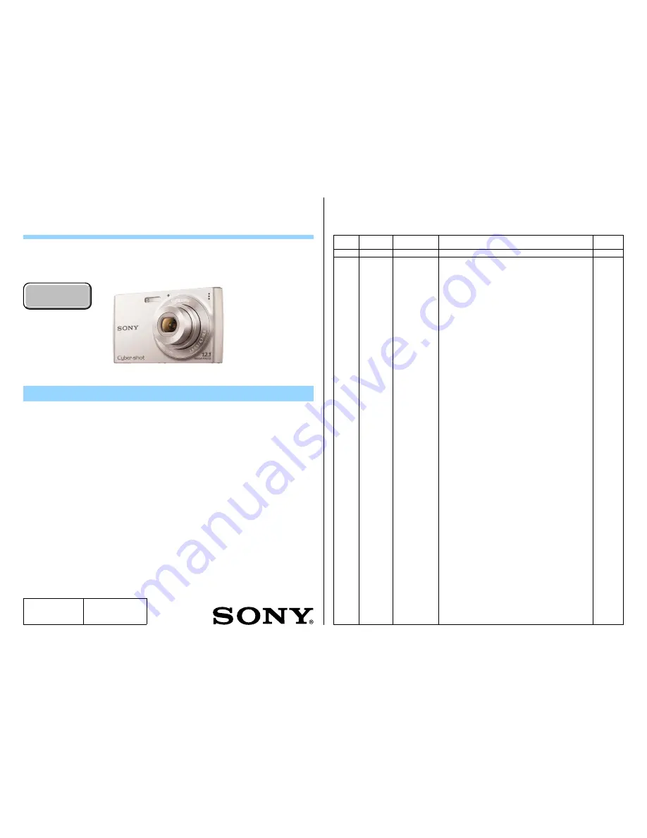
DSC-W510

Sony Corporation

SERVICE MANUAL

Revision History

SERVICE  NOTE (Check the following note before the service.)

983454511.pdf

2010K29-1

  © 2010.11

Published by Sony Techno Create Corporation

Ver. 1.0  2010.11

DIGITAL STILL CAMERA

9-834-545-11

US Model

Canadian Model

AEP Model

UK Model

E Model

Australian Model

Chinese Model

Korea Model

Argentine Model

Brazilian Model

DSC-W510

Ver.

Date

History

Contents

S.M. Rev.

issued

1.0

2010.11

Official Release

Internal memory

ON BOARD

Internal memory

ON BOARD

1-1.  METHOD FOR COPYING OR ERASING THE DATA IN INTERNAL MEMORY

1-2.  DEDICATED A/V CABLE (OPTIONAL ACCESSORY)

1-3.  REGARDING FUSE

1-4.  ORNAMENTAL RING A OR BARRIER ASSY REPLACING METHOD

1-5.  OPTICAL STEPPING MOTOR (F1380) REPLACING METHOD

1-6.  DC MOTOR WORM A ASSY REPLACING METHOD

1-7.  CAM TUBE BLOCK ASSY AND STRAIGHT TUBE LUBRICATED ASSY AND


1 GROUP FRAME REPLACING METHOD

1-8.  FINAL INSPECTION

The  components  identified 

by mark 

0

 or dotted line with 

mark 

0

 are critical for safety.

Replace only with part number 

specified.

Les  composants  identifiés  par 

une  marque 

0

  sont  critiques 

pour la sécurité.

Ne les remplacer que par une 

pièce portant le numéro spécifié.

Photo: Silver

Summary of Contents for Cyber-shot DSC-W510

Page 1: ...l memory ON BOARD 1 1 METHOD FOR COPYING OR ERASING THE DATA IN INTERNAL MEMORY 1 2 DEDICATED A V CABLE OPTIONAL ACCESSORY 1 3 REGARDING FUSE 1 4 ORNAMENTAL RING A OR BARRIER ASSY REPLACING METHOD 1 5 OPTICAL STEPPING MOTOR F1380 REPLACING METHOD 1 6 DC MOTOR WORM A ASSY REPLACING METHOD 1 7 CAM TUBE BLOCK ASSY AND STRAIGHT TUBE LUBRICATED ASSY AND 1 GROUP FRAME REPLACING METHOD 1 8 FINAL INSPECTI...

Page 2: ... PARTS WHOSE PART NUMBERS APPEAR AS SHOWN IN THIS MANUAL OR IN SUPPLEMENTS PUBLISHED BY SONY ATTENTION AU COMPOSANT AYANT RAPPORT À LA SÉCURITÉ LES COMPOSANTS IDENTIFIÉS PAR UNE MARQUE 0 SUR LES DIAGRAMMES SCHÉMATIQUES ET LA LISTE DES PIÈCES SONT CRITIQUES POUR LA SÉCURITÉ DE FONCTIONNEMENT NE REM PLACER CES COMPOSANTS QUE PAR DES PIÈCES SONY DONT LES NUMÉROS SONT DONNÉS DANS CE MANUEL OU DANS LES...

Page 3: ...tly erases all data on the memory card and is unrecoverable Save precious data on a computer etc 1 MENU t Settings t Memory Card Tool or Internal Memory Tool t Format t OK t z Note Note that formatting permanently erases all data including even protected images Copy Copies all images in the internal memory to a memory card 1 Insert a memory card with sufficient free capacity into the camera 2 MENU...

Page 4: ...Screw Screw Screw Screw Rear Mirror Plate 1 4 ORNAMENTAL RING A OR BARRIER ASSY REPLACING METHOD 3 4 INSTALLATION 1 Note The tape must not be wrinkled 2 5 Ornamental Ring A Barrier Assy A REMOVAL 1 Turn on the power switch and extend the lens 2 Detach the battery 3 Pour a solvent such as alcohol from two places A to the tweezers or a needle shown below into a gap of Ornamental Ring A 4 Tweezers Re...

Page 5: ...ews in the order of numbers Screw Screw Screw Screw Rear Mirror Plate Naruto Gear Lubricated Assy Warm B Lubricated Assy 4 1 2 3 Screw Screw Screw FG Seal Screw Screw Screw Rear Mirror Plate Naruto Gear Lubricated Assy Warm B Lubricated Assy Solder DC Motor Worm A Assy Screw Screw FG Seal Solder DC Motor Worm A Assy 1 7 CAM TUBE BLOCK ASSY AND STRAIGHT TUBE LUBRICATED ASSY AND 1 GROUP FRAME REPLAC...

Page 6: ...ubricated Assy and align the two points of ditches of the Straight Tube Lubricated Assy with ditches of the Cam Tube Block Assy then remove the Straight Tube Lubricated Assy from the Cam Tube Block Assy qf Pour a solvent such as alcohol from two places qg Remove while turning the Ornamental Ring A right and left qh Remove Barrier Assy by disengaging four claws qj Remove the bond at the three point...

Page 7: ... Assy Cam Tube Block Assy Eyepiece Side View Eyepiece Side View Eyepiece Side View Ditch Ditch Ditch Ditch Ditch Ledge Ledge 2 Group Assy 2 Group Assy 1 Install the 1 Group Lens Assy to the 1 Group Frame 2 Rotate the 1 Group Lens Assy and align triangular sign with round sign 3 Apply the bond at the three points Note Use the Super X or the equivalent INSTALLATION 6 7 4 Note The tape must not be wr...

Page 8: ...be Block Fixed Stationary Tube Block Fixed Stationary Tube Block Ditch Convex Part Flexible Board Fixed Stationary Tube Naruto Gear Lubricated Assy Naruto Gear Lubricated Assy qj Install the Warm B Lubricated Assy qk Connect the Iris Flexible Board from connector of 2 Frame Assy w Install the 3 Group Frame ql Install the 3 Group Spring wa Tightening torque 0 049 0 01N m 0 5 0 1kgf cm Install the R...

Page 9: ... extreme focus blurring It should be distinguished the black and white by the sharpness between them If it is in NG level replace the lens unit Reference How to Print the Chart Print Forcus Chart_A3 pdf with printer Print at the same magnification It means 100 size Check the settings of printer to print in proper size Check of chart size Make charts together and check if the size of charts is the ...

Page 10: ... Silver Parts Color The components identified by mark 0 or dotted line with mark 0 are critical for safety Replace only with part number specified Les composants identifiés par une marque 0 sont critiques pour la sécurité Ne les remplacer que par une pièce portant le numéro spécifié When indicating parts by reference number please include the board name Abbreviation AR Argentine model AUS Australi...

Page 11: ...off Therefore the remaining voltage must be discharged as described below Preparing the Short Jig To preparing the short jig a small clip is attached to each end of a resistor of 1 kΩ 1 W 1 215 869 11 Wrap insulating tape fully around the leads of the resistor to prevent electrical shock DISCHARGING OF THE CHARGING CAPACITOR Cut and remove the part of gilt which comes off at the point Be careful o...

Page 12: ...K 6 4 273 595 21 BELT R ORNAMENTAL PINK 6 4 273 595 31 BELT R ORNAMENTAL RED S1 4 273 575 01 SCREW_M_1 4_3 5_BLK_AB BLACK RED Note1 S2 4 273 576 01 SCREW_M_1 4_3 5_SVR_AB SILVER PINK Note1 S3 4 273 577 01 SCREW_M_1 4_2 5_BLK_AB BLACK RED Note1 S4 4 273 578 01 SCREW_M_1 4_2 5_SVR_AB SILVER PINK Note1 S5 4 273 593 01 SCREW_M_1 4_2 0_SVR_AB S6 4 273 594 01 SCREW_TP_1 4_4 5_SVR_AB 1 S1 S2 X 6 S3 S4 X ...

Page 13: ...F07 54 X 2580 723 1 PLATE ASSY MICROPHONE GROUND 55 4 273 601 01 COVER CAPACITOR 56 X 2580 724 1 PLATE ASSY SP GROUND S7 4 273 597 01 SCREW_TP_1 4_3 5_SVR_AB 1 Remove to numerical order 8 to qa in the left figure qa Unsolder qa S7 X 2 8 Raise the LCD Module 8 S7 X 2 S7 Back View LCD Module S7 Back View Top View Solder 53 9 8 52 54 11 Solder S7 S7 qa 8 qa 51 Main Frame Section See page 2 5 56 0 55 ...

Page 14: ...15 11 FUSE MICRO 1608 TYPE 2A 32V 0F2 1 576 415 11 FUSE MICRO 1608 TYPE 2A 32V S7 4 273 597 01 SCREW_TP_1 4_3 5_SVR_AB DISASSEMBLY 1 Remove to numerical order qs to qg in the left figure qd Unsolder qd 1 Unsolder qd 2 S7 X 1 qs S7 X 1 Remove the Ground Plate qs 1 Remove the Cushion 1 qs 2 and Cushion 2 qs 3 Back View qs 2 qs 3 S7 Note Note1 Refer to Assembly 1 Routing Method of the Microphone Lead...

Page 15: ... S8 3 086 156 11 SCREW B1 2 S9 3 947 504 31 SCREW M1 2 Note Note2 Refer to the following each item when you exchange parts of Lens Block 1 4 ORNAMENTALRINGAOR BARRIERASSYREPLAC ING METHOD page 1 2 1 5 OPTICAL STEPPING MOTOR F1380 REPLACING METHOD page 1 2 1 6 DC MOTOR WORM A ASSY REPLACING METHOD page 1 3 1 7 CAM TUBE BLOCK ASSY AND STRAIGHT TUBE LUBRICATED ASSY AND 1 GROUP FRAME RE PLACING METHOD...

Page 16: ...2P Adaptor 0 1 569 008 14 E Central South America Cyber shot User Guide HTML About Cyber shot User Guide HTML This CD ROM is provided in HTML Therefore it is suitable for browsing on the PC but is not suitable for printing The printed matter is not supplied The following lists part numbers of languages The CD ROM supplied contains all of language version 4 264 975 11 ENGLISH 4 264 975 21 FRENCH 4 ...

Page 17: ...rough the hole of the Main Frame Assy Top View Speaker lead wire Microphone lead wire Assembly 2 Assembling Method of the BT Terminal Main Board Assy Main Frame Assy 2 1 Insert the BT Terminal vertically into the holder of the Main Frame Assy 2 2 Attach the Main Board Assy to the Main Frame Assy and solder the BT Terminal at three points shown below Soldering point BT Terminal ...

Page 18: ...DSC W510 4 1E 4 BLOCK DIAGRAMS 4 1 OVERALL BLOCK DIAGRAM ...

Reviews: