— 1 —
Model Name Using Similar Mechanism
NEW
CD Mechanism Type
CDM-40
Base Unit Type
KSM-213BKN/M-N
Optical Pick-up Type
KSS-213B/S-N
MICROFILM
COMPACT DISC PLAYER
CDP-CX200
SERVICE MANUAL
US Model
Canadian Model
AEP Model
UK Model
E Model
Australian Model
PX Model
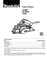
SPECIFICATIONS
E, PX
Australia
240V AC, 50Hz
120V AC, 60Hz
220V - 230V AC, 50Hz
USA, Canada
Europe and Singapore
Summary of Contents for CDP-CX200
Page 5: ... 5 PX This section is extracted from instruction manual ...
Page 6: ... 6 ...
Page 7: ... 7 ...
Page 8: ... 8 ...
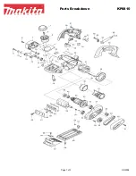
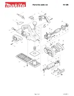
Page 11: ... 11 3 5 BASE UNIT ASSEMBLY 1 Screw BVTT3x6 2 Fulcrum plate BU UPPER assy 3 Base unit ...
Page 27: ......
Page 28: ......
Page 29: ......
Page 30: ......
Page 31: ......
Page 32: ......
Page 48: ......
Page 49: ......
Page 50: ......
Page 51: ......
Page 52: ......
Page 53: ......
Page 54: ......
Page 55: ......
Page 56: ......
Page 57: ......
Page 58: ......
Page 59: ......
Page 60: ......
Page 61: ......
Page 62: ......
Page 63: ......
Page 64: ......
Page 65: ......
Page 66: ......
Page 67: ......