Sony 4-105-930-12(1), Operating Instructions Manual
The Sony 4-105-930-12(1) Operating Instructions Manual is a comprehensive guide that provides detailed instructions for operating your Sony product. It is available for free download on our website, ensuring easy access to the manual you need. Visit manualshive.com to get your user manual and unlock the full potential of your Sony device.
Share
Download


Reviews:
No comments
Related manuals for 4-105-930-12(1)
EF 24mm f/2.8 IS USM
Brand: Canon Pages: 2
EF14mm f/2.8L II USM
Brand: Canon Pages: 2
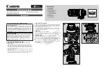
EF24-105MM F/4L IS USM
Brand: Canon Pages: 21
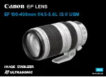
EF100-400mm f/4.5-5.6L IS II USM
Brand: Canon Pages: 21

Speedlite 600EX-RT
Brand: Canon Pages: 2
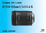
EF-S18-135mm f/3.5-5.6 IS STM
Brand: Canon Pages: 11
Speedlite 420EX
Brand: Canon Pages: 13
EF 70-200mm f/2.8L IS II USM
Brand: Canon Pages: 2
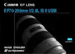
EF 70-200mm f/2.8L IS II USM
Brand: Canon Pages: 17
Macro Twin Light MT-26EX-RT
Brand: Canon Pages: 128
Speedlite 600EX-RT
Brand: Canon Pages: 372

EXPCMR-ALG-OZ-IC-1080PLE1-1227-250C-QD-15C-12.4
Brand: LARSON Pages: 4
EF-S10-18mm f/4.5-5.6 IS STM
Brand: Canon Pages: 16
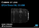
EF24-70mm f/2.8L USM
Brand: Canon Pages: 11

HS1450CCD
Brand: Mini Gadgets Pages: 6

VSC21203
Brand: VS2 Pages: 2

DWC-MV421TIRB
Brand: Digital Watchdog Pages: 2

M5054
Brand: Axis Pages: 26


