background image


7/10/2009  


OWNER'S MANUAL

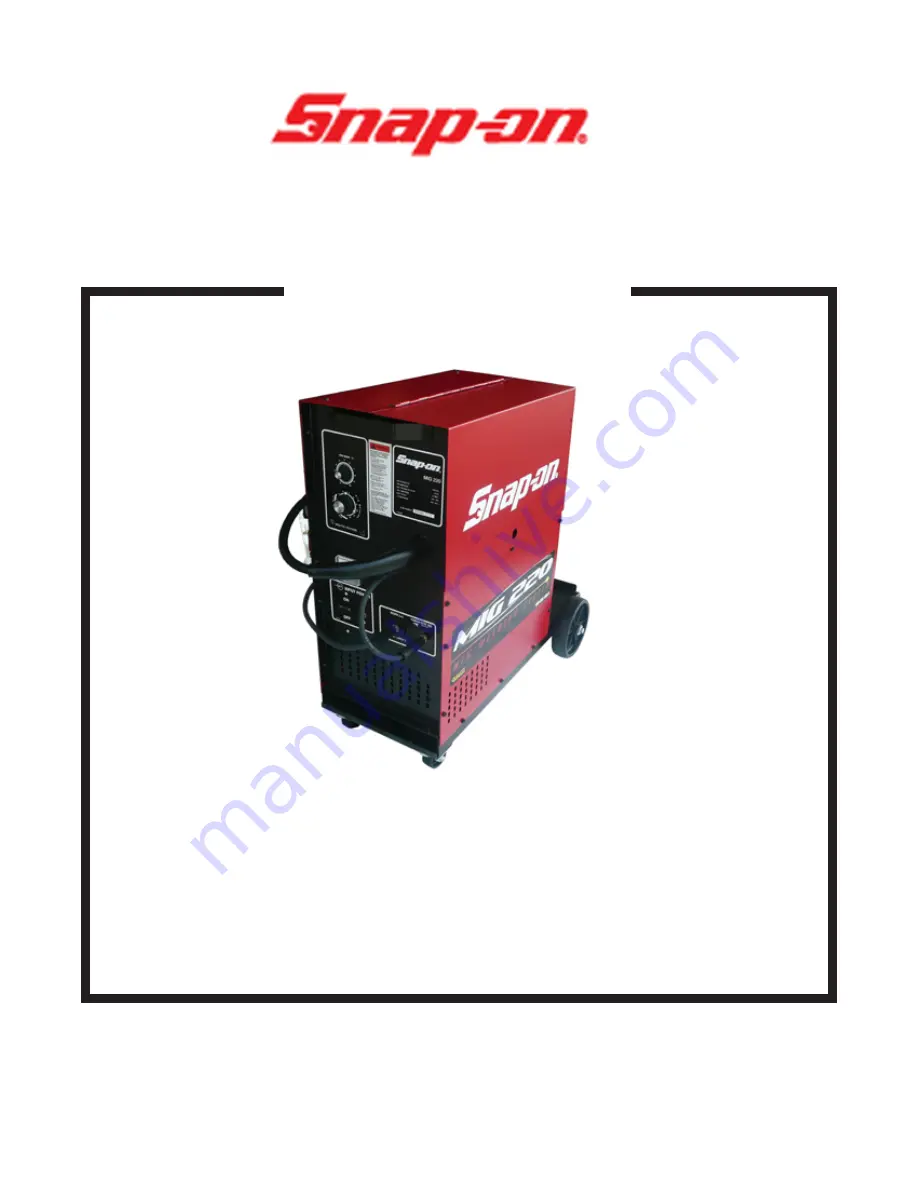
THE MIG220 REPRESENTS THE LATEST TECHNOLOGY
IN MIG COMBINATION UNITS.  THE MIG220 OPERATES ON

 SINGLE PHASE CURRENT, AND FEATURES "SMOOTH ARC" 

 TRANSFORMER DESIGN CONCEPT.

MIG220

MIG COMBINATION UNIT

FOR TECH. SERVICE, CALL


Or


 WWW.800ABCWELD.COM

 At

 Web

 The

 On

 Us


Visit


 Toll-Free 1-800-222-9353


FORM 

INSTALLATION

OPERATION

MAINTENANCE


Summary of Contents for MIG220

Page 1: ...IG COMBINATION UNITS THE MIG220 OPERATES ON SINGLE PHASE CURRENT AND FEATURES SMOOTH ARC TRANSFORMER DESIGN CONCEPT MIG220 MIG COMBINATION UNIT FOR TECH SERVICE CALL Or WWW 800ABCWELD COM At Web The On Us Visit Toll Free 1 800 222 9353 FORM INSTALLATION OPERATION MAINTENANCE ...

Page 2: ...AMAGES SO THE ABOVE LIMITA TIONS OR EXCLUSIONS MAY NOT APPLY TO YOU THIS WARRANTY GIVES YOU SPECIFIC LEGAL RIGHTS AND YOU MAY HAVE OTHER RIGHTS WHICH MAY VARY FROM STATE TO STATE ARC WELDING CAN BE INJURIOUS TO OPERA TOR AND PERSONS IN THE WORK AREA CONSULT INSTRUCTION MANUAL BEFORE OPERATING ELECTRIC SHOCK can kill Do not touch electrodes or other electrically live parts Insulate yourself from wo...

Page 3: ...eld The emerging wire and the weld are shielded by a stream of CO2 Argon or a mixture of the two which prevents oxidation of the molten weld puddle The gas shield enables high quality welds to be made without the use of flux eliminat ing the need for slag or flux removal after the weld is com pleted POWER SOURCE WIRE SPOOL FEED ROLLS WORK MIG TORCH REVERSE POLARITY STD _ SHIELDING GAS ELEC TRODE W...

Page 4: ... tap switch providing twelve volt age selections Voltages can be monitored by the voltmeter on the control panel Wire feed speed is controlled by the wire speed poten tiometer SPECIFICATIONS PART NUMBER MIG220 INPUT POWER REQUIREMENTS Voltage 208 230 volts AC single Phase phase Frequency 50 60 hertz Current cycle duty 60 26 24 amps NOTE This welder draws 20 amps at 100 Duty cycle 140 amps output A...

Page 5: ...CIFICATIONS NECK ANGLE 60 degrees LEAD LENGTH 10 feet OVERALL LENGTH 10 feet COOLING METHOD gas air RATING DUTY CYCLE With Argon CO2 gas150 amps 100 With CO2 gas 200 amps 100 CHECK LIST THE SNAP ON TOOLS MIG220 INCLUDES THE FOLLOWING 1 Combination Power Source Wire Feeder 1 Cylinder Rack Industrial Wheel Kit 1 15TG10 MIG Torch with adjust able nozzle 1 20 foot Power Input Cable 1 10 foot Ground Ca...

Page 6: ...nce ELECTRICAL SUPPLY Ensure that there is a 208 or 230 volt single phase 40 amp elec trical supply within easy reach of the unit The input cable supplied is 20 feet long A 50 foot cable is an optional extra Attach a suit able plug making sure the green wire is attached to ground All wiring should be performed by a qualified electrician 230V INPUT SELECTION 1 Factory selected no change is needed M...

Page 7: ... a wrench Open the cylinder valve When welding steel the gas flow rate is 30 CFH When welding aluminum the gas flow rate is 40 CFH NOTE TORCH 1 2 and panel front the on month panel torch the into MIG the Insert chine ma the inside bracket mounting assembly drive the on located screw thump the out Back extent fullest its to machine the of door access the Open CONNECTION adjusted be can rate flow ga...

Page 8: ... guide over the feed roll and into the torch liner Ensure that the wire locates in the feed roll groove Do not allow the wire on the spool to loosen 9 Close and relatch the pressure roll arm 10 Stretch the torch cable straight out in front of the machine making sure there are no kinks Remove the nozzle and contact tip from the torch 11 Turn on the circuit breaker on the front of the machine The co...

Page 9: ...e contact tip should be flush or stick out up to 1 16 inch beyond the end of the nozzle For aluminum the con tact tip should be recessed 1 8 to 3 8 inch inside the nozzle Using wire cutters trim off the wire so the stickout is approxi mately 1 4 inch for steel or 1 inch for aluminum For aluminum the end of the wire should be bent over so it does not JAM into the work This is called a scratch start...

Page 10: ...ctice on scrap metal of the same type and thickness as the material to be welded OPERATING SEQUENCE 1 Make sure that the pieces of metal to be welded are free of grease dirt paint and scale Use a wire brush to remove paint and scale Paint must be com pletely removed to bare metal Grease and oil could burn and cause a fire or safety hazard Failure to clean the metal prop erly will result in erratic...

Page 11: ...SPEED Potentiometer controls speed of wire drive motor to give wire speed range of 10 to 500 inches per minute B HEAT VOLTAGE CONTROL Twelve position switch adjusts welder output voltage C VOLTMETER Indicates open circuit voltage when torch switch is actuated and arc voltage while welding D CIRCUIT BREAKER Primary power switch and over load protection device E ON INDICATOR LIGHT Illuminates when t...

Page 12: ...pproximately 3 8 inch This helps prevent the welding wire from burning back to the contact tip 4 Use a welding helmet with a shade 9 to 11 filter lens depending on operator preference 5 Squeeze the torch trigger The wire will feed and an arc will be established As the weld is deposited move the torch slowly along the weld seam at a constant speed while maintaining a con stant arc length and a cons...

Page 13: ...and the nozzle can cause a short circuit and consequently failure of the torch or welding machine The frequent use of anti spatter spray will help prevent the adher ence of spatter to the torch compo nents NOTE DO NOT use any anti spatter spray when welding aluminum or stainless steel Restricted gas flow holding the torch too far from the work piece and the use of CO2 gas rather than 75 Argon 25 C...

Page 14: ... extin guisher or other fire protec tive device NEVER weld on a closed vessel or one that has contained combustibles IF IN DOUBT DON T DO IT BE SAFE DON T BE SORRY WARNING 2 Remove dirt and metal deposits from the grooves in the feed roll If the grooves are badly worn the feed roll should be replaced If the pressure roll does not turn freely it should be replaced 3 Check all gas fittings for leaks...

Page 15: ...ose or broken connection Check or repair on wiring harness connections Wire feed motor unplugged Plug in motor RC3 Faulty control transformer Check for 28VAC output T2 Main power on Pressure roll arm unlatched Latch arm add tension torch Slippage at drive rolls Increase drive roll trigger tension See page 7 activated Wire path restricted Clean path or replace no wire feed torch liner but contactor...

Page 16: ...retry Faulty diodes Check diodes See page D1 D4 16 Torch No shielding gas Replace tank trigger tank empty activated Loose or broken Tighten or repair no gas flow connections connections but contactor Faulty Gas solenoid Repair or replace operates valve GS valve wire feeds Clogged gas flow path Locate clean clog FAULTY WELDS Jerky or Worn kinked or dirty torch Clean or replace slipping liner liner ...

Page 17: ...old torch closer to work Poor connections Check and tighten all connections Faulty diode Test diodes replace D1 D4 faulty diode s See page 16 Heavy spatter Incorrect machine settings Increase heat decrease wire feed speed Incorrect shielding gas Replace with proper gas Excessive wire stick out Hold torch closer to work Porous welds No shielding gas Turn on gas Not enough gas flow Check hoses for l...

Page 18: ...ed If there is continuity in one direction only the diode is functioning properly 3 If all the diodes check out satisfactorily with the Volt Ohm Meter a load check must be made using a twelve volt battery and a twelve volt headlight bulb CAUTION NEVER use a megger or a high voltage device to test a diode 4 Connect the headlight bulb to one end of the diode Test for electrical flow in both directio...

Page 19: ... IS REQUIRED 1 Remove the top cover assembly from the unit 2 Locate the printed circuit board 3 Referring to Figure 17 locate the trim resistor this is lo cated in the upper right hand corner of the wire feed PC board 4 Turn the wire speed dial on the front of the machine to 0 5 Remove any tension on the drive roll 6 Activate the torch trigger 7 Rotate the trim resistor back and forth until the bo...

Page 20: ...rectly to the gas regulator CONNECTING TIGPAK OR SPOOL GUN NOTE Make sure the regulator is connected to a cylinder of the proper shielding gas pure argon for TIG welding NOTE Make sure the gas regulator and welder gas hose are connected to a cylinder of the proper shielding gas 100 argon for aluminum welding 75 argon 25 CO2 for steel welding 98 argon 2 O2 is recommended for stainless steel welding...

Page 21: ... the gas diffuser Spray the O rings with anti spatter com pound for lubrication 10 Install the TWIST ON adjustable nozzle and twist the nozzle during the installation Turn to Page 7 for correct nozzle ad justment 4 Install the new liner into the MIG torch assembly until gas seal seats flush with the con nector plug 5 Tighten set screw Do not over tighten refer to FIG 20 6 Following the diagram in ...

Page 22: ...IFICE 1 2 Longer 1 Longer WIRE SIZE PARTNUMBER CUP PARTNUMBER PARTNUMBER PARTNUMBER CUP 1 2 I D M3 C50L M3 C50XL INS BUSHING M3H B 020 025 inch M3 ST25 Flared CONTACT TIP NOZZLE NUT M3H NN 030 inch M3 ST30 Cup 020 025 inch M5 T25 M5 LT25 SPOT NOZZLE 035 inch M3 ST35 5 8 I D 030 inch M5 T30 M5 LT30 FlatSpot M3H NS1 040 047 inch M3 ST45 M3 C62 035 inch M5 T35 M5 LT35 InsideCorner M3H NS2 040 047 inc...

Page 23: ...WITH ADJUSTING SCREW TRIGGER PIN TRIGGER SPRING QUICK CONNECTOR GROUP M3 120 FERRULE M3 301A CONNECTOR HOUSING M3 305A CONNECTOR STEM M3 306 CONNECTOR PLUG WITH SETSCREW O RINGS M3 307 SETSCREW ONLY M3 308 O RING ONLY 2 REQUIRED M3 309 TERMINAL CONNECTOR CONTACT 2 REQUIRED M3 310A BOOT CABLE SUPPORT M1 401 HANDLE M3 402 HANDLE SCREW 2 REQUIRED M3 405 TERMINAL TORCH END 2 REQUIRED M3 406 TERMINAL C...

Page 24: ...3 Thru 3 64 diameter wire from 4 inch spools The standard equipment cable is 25 feet in length 35 foot and 50 foot cables are optional The wire speed control knob is in the gun handle With the following options the MHG5 A can be used to weld steel or stainless steel 030 035 diameter wire sizes SN 2160K Knurled Drive Roll for 030 035 steel wire M5 T30 Contact Tip for 030 steel wire or M5 T35 Contac...

Reviews: