Smith Medical LEVEL 1 HOTLINE 3 HL-390-38, Operator'S Manual
The Smith Medical LEVEL 1 HOTLINE 3 HL-390-38 is a cutting-edge medical device that requires careful operation. Ensure safe and effective use by referring to the Operator's Manual available for free download on our website. Download the manual from manualshive.com for proper guidance on using this innovative product.
Share
Download


Reviews:
No comments
Related manuals for LEVEL 1 HOTLINE 3 HL-390-38
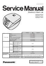
SR-DF101
Brand: Panasonic Pages: 41

200-1R
Brand: Wittco Pages: 24

Proofer/Hot Cabinet PHC70-MP17
Brand: BevLes Pages: 2

SM44 HS
Brand: siat Pages: 84

DHWBI Series
Brand: Hatco Pages: 28

DB-2-HF
Brand: Piper Products Pages: 13

3M-MATIC 8000a-T
Brand: 3M Pages: 178

SB-2EX-SEMI
Brand: Eastey Pages: 58

FW-CN-0001
Brand: Omcan Pages: 16

6060A
Brand: Nemco Pages: 2

FW-US-690-25-2
Brand: Omcan Pages: 16

Thermasonic Series
Brand: Parker Laboratories Pages: 2

X-PW01-EUR
Brand: X-pole Pages: 8

27 51 31
Brand: Westfalia Pages: 3

F20-BI
Brand: Piper Products Pages: 33

2000161
Brand: VonShef Pages: 8

688.130
Brand: CaterChef Pages: 26

D-504
Brand: Signode Pages: 2


