Smeg GW01160S, User Manual
Get the most out of your Smeg GW01160S with the comprehensive user manual. Available for free download at manualshive.com, this manual provides step-by-step instructions, troubleshooting tips, and useful information. Enhance your appliance experience with this invaluable resource, ensuring seamless operation and optimal performance.
Share
Download


Reviews:
No comments
Related manuals for GW01160S
GTD42EASJWH
Brand: GE Pages: 24
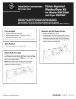
WNCD2050
Brand: GE Pages: 2

K 2 Premium Horizontal
Brand: Kärcher Pages: 132

WD11J8 Series
Brand: Samsung Pages: 96

Conservator 3953964
Brand: Crosley Pages: 12

SteamScrubber 4010010 Series
Brand: Labconco Pages: 108

520 MH
Brand: Kärcher Pages: 20

FIDWB16
Brand: Glen Dimplex Pages: 48

DF271100F
Brand: Gaggenau Pages: 68

K 3 Follow Me
Brand: Kärcher Pages: 32

Adora S Series
Brand: V-ZUG Pages: 64

Maxus PW2515
Brand: Campbell Hausfeld Pages: 48

V1250
Brand: FAR Pages: 16

LFA-45X
Brand: Fagor Pages: 26

LMX Artic
Brand: Lavorwash Pages: 34

K 2.99 MH
Brand: Kärcher Pages: 20

HWM7T3l16C
Brand: Hanseatic Pages: 84

LAM8607
Brand: Lamona Pages: 24


