Smarteye Digital Electronics SER-2A Series, User Manual
The Smarteye Digital Electronics SER-2A Series user manual is now available for free download on our website. This comprehensive manual provides detailed instructions and information on operating your device effectively. Get the most out of your product and download the user manual today from manualshive.com.
Share
Download


Reviews:
No comments
Related manuals for SER-2A Series

VVH-MDE52
Brand: Vacron Pages: 2

VVH-MDE31D
Brand: Vacron Pages: 2

VVH-MDE304
Brand: Vacron Pages: 52

HDR 1
Brand: Bang & Olufsen Pages: 56

NDVR
Brand: EverFocus Pages: 152

FXV-H1304
Brand: Felix Storch Pages: 14

2036T/R
Brand: Jesmay Electronics Pages: 13

4 Channel Network Video Recorder
Brand: Entry-Level Pages: 83
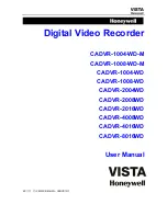
CADVR-1004-WD
Brand: Honeywell Pages: 63

H.264 HRDP
Brand: Honeywell Pages: 106
EVOLUTION 2
Brand: Honeywell Pages: 2

Fusion IV
Brand: Honeywell Pages: 150

FUSION III DVR
Brand: Honeywell Pages: 168

FUSION
Brand: Honeywell Pages: 168

HD-DVR-1004
Brand: Honeywell Pages: 182

HD-16DVR-C
Brand: Honeywell Pages: 169
HDVR
Brand: Honeywell Pages: 238

CADVR-04D
Brand: Honeywell Pages: 240


