background image

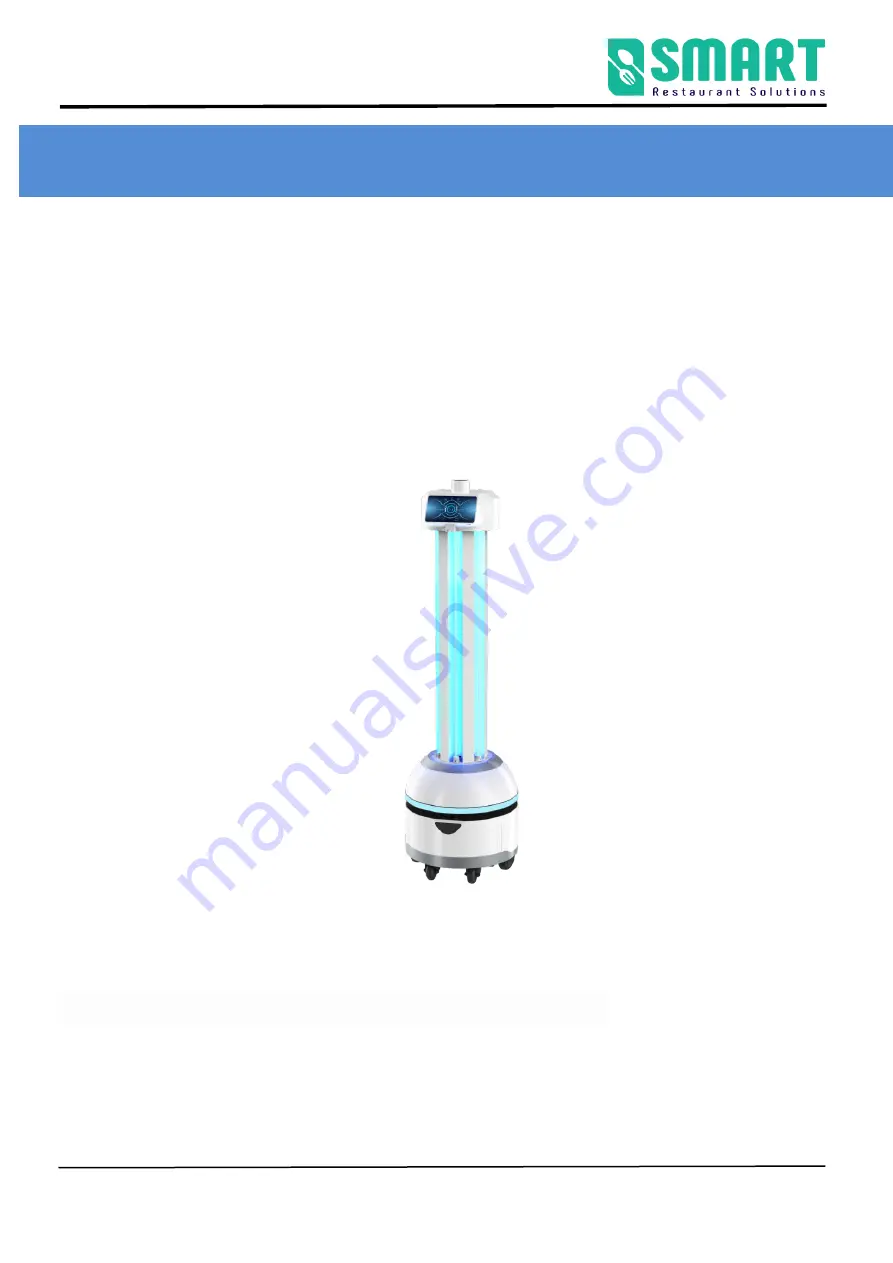
UVC Disinfection Robot Manual 


Smart Restaurant Solutions 


Spark UVC Disinfection Robot Manual 


Version

2.1.4 G 

Date: December 27, 2021 


Note

:

This document provides the deployment process and precautions 

related to the machine. The use 

method indicated in the document can avoid the abnormal situation during the later use of the machine. 


Summary of Contents for Spark UVC

Page 1: ...VC Disinfection Robot Manual Version 2 1 4 G Date December 27 2021 Note This document provides the deployment process and precautions related to the machine The use method indicated in the document ca...

Page 2: ...eters 5 Meet your robot 8 2 Use your robot 9 A Boot 9 B Charging 10 C Navigation deployment 13 The step 1 Network Settings 13 The step 2 Build a map 14 The Step 3 Position 21 The step 4 Virtual wall 2...

Page 3: ...UVC Disinfection Robot Manual Smart Restaurant Solutions 3 5 Precautions for use 36 Lost of robot positioning 36 The robot does not navigate 38 The machine navigation does not respond to charging 39...

Page 4: ...lective cabinets at the floor height of 30 cm Do not travel on the ground with high friction thicker softer carpet Do not use the robot in an environment with a slope greater than 5 Do not use the rob...

Page 5: ...d rolled steel sheet Environmental requirements Storage temperature 15 C 55 C Working temperature 10 C 50 C Humidity RH 10 90 Infrared camera Two dimensional code positioning the height of the two dim...

Page 6: ...work 11ac 5 15GHz 5 825GHz ROS navigation specifications Lidar Laser wavelength 905 nm working area 270 Single axis gyroscope Sensor Yaw angle measurement Hard disk 32G high speed solid state drive Mo...

Page 7: ...5A Optional Battery 37 V 20 AH lithium battery Charging pile parameters Overcurrent protection intelligent power off output rated voltage 42VDC output rated current 3A 5A optional Remote function Sup...

Page 8: ...hine coordination ability automatic obstacle avoidance and other functions It can automatically navigate to a designated location indoors The following is the body structure of UV disinfection robot I...

Page 9: ...he laser with objects Emergency stop switch the emergency stop switch can only be rotated to the right do not rotate to the left 2 Use your robot A Boot The power button is located on the base on the...

Page 10: ...dapter plug needs to be plugged into the 110 220V voltage and the DC head is plugged into the automatic charging pile At this time the green light of the charging pile will be on indicating that it is...

Page 11: ...UVC Disinfection Robot Manual Smart Restaurant Solutions 11 Direct charging plug the power adapter cable into the power supply on the back of the robot Automatic charging hardware description...

Page 12: ...UVC Disinfection Robot Manual Smart Restaurant Solutions 12 Placement of charging pile Notes on the selection of charging pile location...

Page 13: ...s 1 2 3 and 4 in the following figure Other functions depend on the specific scenarios and usage conditions The step 1 Network Settings Note The router network segment cannot be the 192 168 10 x netwo...

Page 14: ...tedly If show IP connection succeeds If shows 127 0 0 1 connection fails 3 The scanning device should be connected to the same LAN as the robot Open the browser and input the IP address of the robot C...

Page 15: ...gation process the robot can compare with the original map based on the real time scanning situation and find its own position The viewing angle of the Lidar is 270 and the scanning range is the horiz...

Page 16: ...igate the specific reason 1 Please follow the order of the figure below to enter the building page get IP from FTP software Mapping method You can turn on the emergency stop switch and click the butto...

Page 17: ...tion to the gaps during walking Slowly turn the robot 90 facing the gaps to clear the feature points then slowly turn back to continue scanning open areas can follow the U shaped route as follows 3 Wh...

Page 18: ...ghosting and matches the actual terrain If there is no obvious dislocation click Finish If there is any dislocation please wait for a period of time and the algorithm will correct it If the correction...

Page 19: ...ther you need to use this method Positioning QR code deployment requirements 1 The ceiling is parallel to the ground and does not reflect light 2 The ceiling shall be flat and it is better to apply pa...

Page 20: ...ted QR code paste method Pasting method as shown in Figure 2 first tear off the white paper of the QR code label paste the transparent surface onto the ceiling and then tear the transparent surface ta...

Page 21: ...ns Note The calibrated position must be at least 50 cm away from surrounding obstacles and virtual walls the machine must be turned on within 2m of the charging pile for subsequent use Schematic diagr...

Page 22: ...iving route Cur position The current position of the robot can be obtained for location calibration Charging pile point the charging shrapnel of the robot directly to the shrapnel of the charging pile...

Page 23: ...oning of the machine is correct 2 The calibrated position must be at least 50 cm away from surrounding obstacles and virtual walls 3 It is recommended that there are no obstacles within 1 5 meters on...

Page 24: ...button and the virtual wall in this area will be cleared Draw curves you can draw a curve which is often used to draw irregular terrain Draw line click two positions to draw a straight line between t...

Page 25: ...to click Save to take effect Example glass wall Note the laser can penetrate the glass so when drawing the virtual wall pay attention to the virtual wall outside the glass figure 1 Actual environment...

Page 26: ...hine is 80cm so attention should be paid when drawing the virtual wall 2 The main function of the virtual wall is to draw the robot s moving space and separate the areas where the robot does not want...

Page 27: ...to draw a polygon at will and a naming box for the area will pop up after completion to define the area and speed Modify adjust the edited speed area click on the speed area that needs to be edited t...

Page 28: ...l areas Note After editing is completed click Save to take effect b Modify map The function of modify map correcting the errors in scanning map Modify premise The map has changed after the scan is com...

Page 29: ...p Do not remove the real obstacles Blocked area some real fixed obstacles may not be scanned very clearly when building the map so it is necessary to draw obstacles artificially on the map note that t...

Page 30: ...view map click to show original image Note The map will not be applied immediately after uploading you need to find the row of the map in All Maps and click the Apply icon d Upgrade Tip We will upgrad...

Page 31: ...UVC Disinfection Robot Manual Smart Restaurant Solutions 31 later Apply this version Delete this version e Debug Power on turn on 36V external power supply...

Page 32: ...be combined Import Import the assembled pgm file Greate new map click to generate a new map Power board upgrade when it ship out of factory is latest version no need to update again Tools of map Func...

Page 33: ...cing map 2 to map 1 to get map 3 import map 3 pgm format into map 1 and then click in Figure 1 Greate new map the generated new map will be automatically downloaded to the computer and finally go to t...

Page 34: ...isinfection robot people and animals should stay away from the UV irradiation area and do not stare at directly at the UV light lamp The best temperature for ultraviolet disinfection and sterilization...

Page 35: ...ultraviolet disinfection robot is gradually reduced during long time use the ultraviolet radiation flux should be measured regularly The lamp is recommended to be replaced after 8000h time use In dai...

Page 36: ...n robot working will match the current map according to the actual laser data If the current terrian environment in big difference from the map build by laser the robot will fail to match the map resu...

Page 37: ...l_ Mark Name c0189 indicates that the mark code has been sensed and the machine has completed relocation At this time turn on the emergency stop switch to continue tasks Note the number of c0189 label...

Page 38: ...avigated only when the robot is turned on Turn the emergency stop switch to the right to indicate on and press to indicate off Check whether the robot has lost its location the orange laser and black...

Page 39: ...the target point When setting it it should be about 50cm away from the obstacle or the virtual wall The machine navigation does not respond to charging Overview send autonomous return charging command...

Page 40: ...UVC Disinfection Robot Manual Smart Restaurant Solutions 40 Remove all obstacle within 1 5m on the left and right sides of the charging pile...

Reviews: