background image

Si5332-AM1/2/3 Automotive Grade Device
Reference Manual

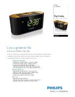
The Si5332-AM1/2/3 is a family of high-performance, low-jitter clock generators capable
of synthesizing five independent banks of user-programmable clock frequencies up to
333.33 MHz, while providing up to 12 differential or 24 single-ended output clocks.
The Si5332 supports free run operation using an external crystal as well as lock to an
external clock signal. The output drivers are configurable to support common signal for-
mats, such as LVPECL, LVDS, HCSL, and LVCMOS. Separate output supply pins allow
supply voltages of 3.3 V, 2.5 V, 1.8 V and 1.5 V (CMOS only) to power the multi-format
output drivers. The core voltage supply (VDD) accepts 3.3 V, 2.5 V, or 1.8 V and is inde-
pendent from the output supplies (VDDOs). Using its two-stage synthesis architecture
and patented high-resolution Multisynth technology, the Si5332 can generate three fully
independent/non-harmonically-related bank frequencies from a single input frequency.

÷ P

PFD

LF

÷M

n

/M


÷R

÷R

÷R

÷R

÷R

÷R

÷R

÷R

÷R

÷R

÷R

÷R

÷N

0

÷N

1

÷O

0

÷O

1

÷O

2

÷O

3

÷O

4

1-31

10-255

10-50 MHz

2.375-2.625 GHz

10-255

8-255

10-250 MHz

10-250 MHz

10-312.5 MHz

10-312.5 MHz

10-312.5 MHz

10-312.5 MHz

10-312.5 MHz

1-63

10-50 MHz

10-250 MHz

10-250 MHz

10-250 MHz

10-30 MHz

VDD_XTAL

VDDA

VDDOA

VDDOB

VDDOC

VDDOD

VDDOE

XA/CLKIN_1

XB

CLKIN_2

nCLKIN_2

CLKIN_3

nCLKIN_3

OUT0

OUT1

OUT2

OUT3

OUT4

OUT5

OUT6

OUT7

OUT8

OUT9

OUT10

OUT11

RELATED DOCUMENTS

• Any-Frequency 6/8/12-output

programmable clock generators

• Offered in three different package sizes,

supporting different combinations of output
clocks and user configurable hardware
input pins

• 32-pin QFN, up to 6 outputs
• 40-pin QFN, up to 8 outputs
• 48-pin QFN, up to 12 outputs

• Multisynth technology enables any

frequency synthesis on any output up to
250 MHz using N dividers.

• Output frequencies up to 333.33 MHz

using O dividers.

• Highly configurable output path featuring a

cross point mux

• Up to three independent fractional

synthesis output paths

• Up to five independent integer dividers
• Down and center spread spectrum
• Input frequency range:

• External crystal: 16 MHz to 50 MHz
• Differential clock: 10 MHz to 250 MHz
• LVCMOS clock: 10 MHz to 170 MHz

• Output frequency range:

• Differential: 5 MHz to 333.33 MHz
• LVCMOS: 5 MHz to 170 MHz

• User-configurable clock output signal

format per output: LVDS, LVPECL, HCSL,
LVCMOS

• Easy device configuration using our

ClockBuilder Pro™

 (CBPro™) software

tool available for download from our web
site

• Temperature range: –40 to +105 °C
• Pb-free, RoHS-6 compliant
• For more information, refer to the 

Si5332

Automotive Grade Data Sheet

Skyworks Solutions, Inc. • Phone [781] 376-3000 • Fax [781] 376-3100 • [email protected] • www.skyworksinc.com

1

Rev. 0.3 • Skyworks Proprietary Information • Products and Product Information are Subject to Change Without Notice • July 26, 2021

1

Summary of Contents for Si5332-AM1

Page 1: ...N_1 XB CLKIN_2 nCLKIN_2 CLKIN_3 nCLKIN_3 OUT0 OUT1 OUT2 OUT3 OUT4 OUT5 OUT6 OUT7 OUT8 OUT9 OUT10 OUT11 RELATED DOCUMENTS Any Frequency 6 8 12 output programmable clock generators Offered in three different package sizes supporting different combinations of output clocks and user configurable hardware input pins 32 pin QFN up to 6 outputs 40 pin QFN up to 8 outputs 48 pin QFN up to 12 outputs Multi...

Page 2: ...ming the Clock Path 21 6 3 Programming the Output Clock Frequency 23 6 4 Programming the Output Clock Format 25 6 5 Programming for Frequency Select Operations 26 6 6 Programming Spread Spectrum 27 7 Si5332 Pinout and Package Variant 29 8 Recommended Schematic and Layout Practices 31 9 Si5332 Common Registers 32 10 Si5332 32 QFN Specific Registers 42 11 Si5332 40 QFN Specific Registers 47 12 Si533...

Page 3: ...configuration and use of A and B divider sets Spread spectrum is available for any clock output sourced from the Multisynth dividers and is available for use in EMI sensitive applications such as PCI Express The 2 wire I2C bus can be used to control and configure the Si5332 Alternatively some device features can be controlled by an external pin via CBPro configuration of one of more General Purpos...

Page 4: ...red part will stop and wait to be configured with outputs disabled Outputs available and stable Time system time delay for PLL clock Time system time delay for Oscillator startup Time system time delay for input clock availability Program Si5332 volatile memory with a frequency plan Time system time delay for NVM download Power supplies for VDDA VDD_DIG and VDD_XTAL stable Is this a blank part Fig...

Page 5: ...e that the external crystal specifications in Si5332 Data Sheet must be met A list of recommended AEC Q200 qualified crystals for the Si5332 can be found in the Silicon Labs document Recommended Crystal Reference Manual for Si5332 Si5357 and Si5225x Automotive Grade Clock Generators Figure 3 1 External Crystal Connection 3 1 2 External Input Clock on XA Input The XA input XA CLKIN1 pin can accept ...

Page 6: ... Differential Input Clock LVDS LVPECL HCSL CML etc Controlled Impedance VDD Core CLKIN_x Figure 3 4 DC Coupled Differential Input Clock To determine if a specific DC coupled differential input clock arrangement is supported refer to the table below Table 3 1 Si5332 Input Clock Coupling Restrictions AC or DC Format VDD_Core 3 3 V 2 5 V 1 8 V LVDS 3 3 V 2 5 V AC or DC AC only AC only LVDS 1 8 V AC o...

Page 7: ...nation is dependent on the driver format used and is usually specified by the driving device and or industry standard clock format specification For example in the case of using a LVCMOS input clock the driving device may recommend a series termination resistor When using LVCMOS input clocks the Si5332 input must be configured in LVCMOS mode in CBPro The single ended CLKIN input of Si5332 is a hig...

Page 8: ...d internal device capacitance CLSINT to match the crystal s requirements A value for CLVAR must be selected such that Required Crystal CL CLVAR CLSINT CLSEXT Or rearranged CLVAR Crystal CL CLSINT CLSEXT Equation 1 Note the required Crystal CL must be greater than or equal to the total stray capacitance quantity CLSINT CLSEXT or the crystal can t be used as CLVAR is always 0 For the following examp...

Page 9: ... Round to nearest integer CLXB 0 485 If 30 555 pF CLXA XB 38 395 pF then Register xosc_cint_ena 1 Register xosc_ctrim_xin Round to nearest integer CLXA 7 84 0 485 Register xosc_ctrim_xout Round to nearest integer CLXB 7 84 0 485 To summarize use Equation 3 to calculate CLXA CLXB then use the above set of formulas to calculate register values to implement CLXA CLXB in the Si5332 Note that external ...

Page 10: ... when using customized Si5332 orderable part numbers OPN generated through CBPro and then either factory programmed or field programmed using the CBPro Field Programming Dongle GPIO pin functionality can be evaluated tested on a Si5332 EVB by downloading a valid CBPro configuration into the EVB and asserting the GPIO pins on the EVB New GPIO configurations or changes to existing GPIO configuration...

Page 11: ... OUTx_MODE Driver Mode 0 off 1 CMOS on positive output only 2 CMOS on negative output only 3 dual CMOS outputs 4 2 5V 3 3V LVDS 5 1 8V LVDS 6 2 5V 3 3V LVDS fast 7 1 8V LVDS fast 8 HCSL 50 Ω external termination 9 HCSL 50 Ω internal termination 10 HCSL 42 5 Ω external termination 11 HCSL 42 5 Ω internal termination 12 LVPECL 13 Reserved 14 Reserved 15 Reserved The recommended termination for each ...

Page 12: ...46 V OUTx OUTx Zo 50 Ω Zo 50 Ω Rs Rs Rs Zo Rdrv Figure 5 2 LVCMOS Termination Option 2 Si5332 AM1 2 3 Automotive Grade Device Reference Manual Output Clock Terminations Skyworks Solutions Inc Phone 781 376 3000 Fax 781 376 3100 sales skyworksinc com www skyworksinc com 12 Rev 0 3 Skyworks Proprietary Information Products and Product Information are Subject to Change Without Notice July 26 2021 12 ...

Page 13: ... receiver RT 2 RT 2 Figure 5 4 LVDS LVDS Fast Termination Option 2 Si5332 AM1 2 3 Automotive Grade Device Reference Manual Output Clock Terminations Skyworks Solutions Inc Phone 781 376 3000 Fax 781 376 3100 sales skyworksinc com www skyworksinc com 13 Rev 0 3 Skyworks Proprietary Information Products and Product Information are Subject to Change Without Notice July 26 2021 13 ...

Page 14: ...1 125 R2 84 LVPECL driver 2 25 V to 3 46 V OUTx OUTx Zo 50 Ω Zo 50 Ω LVPECL receiver R1 R2 R3 Figure 5 6 LVPECL Termination Option 2 Si5332 AM1 2 3 Automotive Grade Device Reference Manual Output Clock Terminations Skyworks Solutions Inc Phone 781 376 3000 Fax 781 376 3100 sales skyworksinc com www skyworksinc com 14 Rev 0 3 Skyworks Proprietary Information Products and Product Information are Sub...

Page 15: ...ode HCSL driver 1 71 V to 3 46 V OUTx OUTx Zo 42 5 Ω or 50 Ω HCSL receiver Zo 42 5 Ω or 50 Ω RT Zo RT Zo Figure 5 8 HCSL External Termination Mode Si5332 AM1 2 3 Automotive Grade Device Reference Manual Output Clock Terminations Skyworks Solutions Inc Phone 781 376 3000 Fax 781 376 3100 sales skyworksinc com www skyworksinc com 15 Rev 0 3 Skyworks Proprietary Information Products and Product Infor...

Page 16: ... 3 LVDS LVDS Fast Termination Option 1 on page 13 through Figure 5 6 LVPECL Termination Option 2 on page 14 can also be converted by adding DC blocking capacitances right before the receiver pins However the recom mendation shown in Figure 5 11 LVDS Termination on page 16 is the simplest way to realize AC coupling i e the least number of components and the recommended circuit for AC coupled termin...

Page 17: ...e used to monitor input clock that controls the PLL The top level block diagram is repeated here to refresh the various limits and possibilities that are necessary for the calculations below P PFD LF Mn Md R R R R R R R R R R R R 1 63 VDD_XTAL VDDA VDDOA VDDOB VDDOC VDDOD VDDOE XA CLKIN_1 XB CLKIN_2 nCLKIN_2 CLKIN_3 nCLKIN_3 OUT0 OUT1 OUT2 OUT3 OUT4 OUT5 OUT6 OUT7 OUT8 OUT9 OUT10 OUT11 N0b N0a N1b...

Page 18: ...VCO s tuning range vcoMinFreq 2 375 GHz The minimum frequency of the VCO s tuning range vcoMaxFreq 2 675 GHz The maximum frequency of the VCO s tuning range List all required output frequencies Fxy in groups denoted by Gx where x 0 1 2 3 4 5 and y a b c This grouping is done such that frequencies related to each other by rational fractions of integers between 1 and 63 are in that group For example...

Page 19: ...ch group and find an integer I that can such that a vcoFreq I LCM can meet the constraint for vcoFreq in Table 6 1 Constraints for PLL Reference Frequency and VCO Frequency b List the L groups that provide a legal vcoFreq i e a vcoFreq that satisfies the condition in step a c Choose the vcoFreq that has most number of performance critical clocks that do not need spread spectrum clocking as part of...

Page 20: ... 30 6 250 15 30 7 175 15 30 8 500 30 50 9 350 30 50 10 250 30 50 11 175 30 50 This algorithm will result in a final solution for a VCO frequency vcoFreq that can then be used to calculate the O divider N divider and R divider values needed to derive each output frequency Foutxy Si5332 AM1 2 3 Automotive Grade Device Reference Manual Programming the Volatile Memory Registers Skyworks Solutions Inc ...

Page 21: ...els of jitter performance Because CMOS outputs have large pk pk swings and do not present a balanced load to the VDDO supplies CMOS outputs generate much more crosstalk than differential outputs For this reason CMOS outputs should be avoided whenever possible When CMOS is unavoidable even greater care must be taken with respect to the above guidelines An output multiplexer output mux or crosspoint...

Page 22: ...q Foutxa Rxa IDxA_INTG Si5332 AM1 2 3 Automotive Grade Device Reference Manual Programming the Volatile Memory Registers Skyworks Solutions Inc Phone 781 376 3000 Fax 781 376 3100 sales skyworksinc com www skyworksinc com 22 Rev 0 3 Skyworks Proprietary Information Products and Product Information are Subject to Change Without Notice July 26 2021 22 ...

Page 23: ... value R2A OUT3_DIV Driver divider ratio 0 disabled 1 63 divide value R2B OUT4_DIV Driver divider ratio 0 disabled 1 63 divide value R2C OUT5_DIV Driver divider ratio 0 disabled 1 63 divide value R3A OUT6_DIV Driver divider ratio 0 disabled 1 63 divide value R3B OUT7_DIV Driver divider ratio 0 disabled 1 63 divide value R3C OUT8_DIV Driver divider ratio 0 disabled 1 63 divide value R4A OUT9_DIV Dr...

Page 24: ...ed 1 63 divide value Si5332 AM1 2 3 Automotive Grade Device Reference Manual Programming the Volatile Memory Registers Skyworks Solutions Inc Phone 781 376 3000 Fax 781 376 3100 sales skyworksinc com www skyworksinc com 24 Rev 0 3 Skyworks Proprietary Information Products and Product Information are Subject to Change Without Notice July 26 2021 24 ...

Page 25: ...om fast to slow 00 fastest 01 slow 10 slower 11 slowest OUTx _cmos_str CMOS output impedance control 0 50 Ω 1 25 Ω Table 6 8 Driver Mode Options drvxy_MODE Driver Mode 0 off 1 CMOS on positive output only 2 CMOS on negative output only 3 dual CMOS outputs 4 2 5 V 3 3 V LVDS 5 1 8 V LVDS 6 2 5 V 3 3 V LVDS fast 7 1 8 V LVDS fast 8 HCSL 50 Ω external termination 9 HCSL 50 Ω internal termination 10 H...

Page 26: ...o bank B Spread spectrum enable fields ID0A_SS_ENA and ID0B_SS_ENA are the only exception and may be enabled disabled while bank is selected 0 bank A 1 bank B In a factory programmed part a pin the FS pin can be used for the same purpose as the control registers Once a control bit is set the backup divider values control the output frequency and that is described by the equations below For O Divid...

Page 27: ...0 5 For center spread of 0 25 then ssc 0 25 The modulation rate also illustrated in the figure below is denoted by Fmod in the equations below For Down Spread Amod ssc 100 For Center Spread Amod 2 ssc 100 idxy_ss_step_num vcoFreq idxy Fmod 4 idxy_ss_step_res Amod idxy_den idxy 128 2 idxy_ss_step_num time frequency F0 Fmax F0 1 ssc 100 Fmin F0 1 ssc 100 Fmod one modulation cycle Fmod one modulation...

Page 28: ...dxy_ss_step_num Number of frequency steps in one quarter SSC modulation period allows for frequency step every output clock idxy_ss_step_intg Divide ratio spread step size idxy_ss_step_res Numerator of spread step size error term idxy_ss_step_den Denominator of spread step size error term To enable SSC idxy_ss_ena needs to be set and the right mode selected in idxy_ss_mode The number of output clo...

Page 29: ... 1 12 Output Si5332 7x7 mm QFN Package Si5332 AM1 2 3 Automotive Grade Device Reference Manual Si5332 Pinout and Package Variant Skyworks Solutions Inc Phone 781 376 3000 Fax 781 376 3100 sales skyworksinc com www skyworksinc com 29 Rev 0 3 Skyworks Proprietary Information Products and Product Information are Subject to Change Without Notice July 26 2021 29 ...

Page 30: ...3 Automotive Grade Device Reference Manual Si5332 Pinout and Package Variant Skyworks Solutions Inc Phone 781 376 3000 Fax 781 376 3100 sales skyworksinc com www skyworksinc com 30 Rev 0 3 Skyworks Proprietary Information Products and Product Information are Subject to Change Without Notice July 26 2021 30 ...

Page 31: ... ii The only filtering needed on each supply node is a 1 μF and a 0 1 μF placed as close as possible to that node iii The Si5332 EVBs have a much larger capacitance on the regulator end mainly to compensate for the regulator loop so that there is no oscillatory behavior from the regulators regardless of the voltage supply value set for that regulator The regulator supply design on the EVB is not r...

Page 32: ...d with USYS_CTRL to confirm device has entered the commanded state i e ACTIVE or READY Reading 0x01 indicates in READY state 0x02 indi cates in ACTIVE state If 0x89 is read this indicates device has not detected an input clock source and can t proceed to ACTIVE state READY ACTIVE UDRV_OE_ENA 8 0 1 RW User master output enable Resets to 1 This bit controls simultaneously the driver start for all dr...

Page 33: ... R The Orderable part number s product revi sion number DESIGN_ID0 17 0 8 R Design identification set by user in CBPro project file READY ACTIVE DESIGN_ID1 18 0 8 R DESIGN_ID2 19 0 8 R I2C_ADDR 21 0 7 R I2C mode device address Reset value is 110_1010 binary I2C_SCL_PUP_ENA 23 0 1 RW Enable 50 kΩ pullup resistor on SCL pad READY ACTIVE I2C_SDA_PUP_ENA 23 1 1 RW Enable 50 kΩ pullup resistor on SDA p...

Page 34: ...ects output mux clock source for output clocks in group G1 OUT1 for AM1 AM2 0 HSDIV0 1 HSDIV1 2 HSDIV2 3 HSDIV3 4 HSDIV4 5 ID0 6 ID1 7 Clock from OMUX1_SEL0 Note that the OMUX1_SEL1 value is forced to 7 whenever the PLL is disabled READY ACTIVE OMUX2_SEL0 27 0 2 RW Selects output mux clock source for output clocks in group G2 OUT2 for AM1 OUT2 OUT3 for AM2 0 PLL reference clock before pre scaler 1...

Page 35: ...4 3 RW Selects output mux clock source for output clocks in group G3 OUT3 for AM1 OUT4 OUT5 for AM2 0 HSDIV0 1 HSDIV1 2 HSDIV2 3 HSDIV3 4 HSDIV4 5 ID0 6 ID1 7 Clock from OMUX3_SEL0 Note that the OMUX3_SEL1 value is forced to 7 whenever the PLL is disabled READY ACTIVE OMUX4_SEL0 29 0 2 RW Selects output mux clock source for output clocks in group G4 OUT4 for AM1 OUT6 for AM2 0 PLL reference clock ...

Page 36: ... mux clock source for output clocks in group G5 OUT5 for AM1 OUT7 for AM2 0 HSDIV0 1 HSDIV1 2 HSDIV2 3 HSDIV3 4 HSDIV4 5 ID0 6 ID1 7 Clock from OMUX5_SEL0 Note that the OMUX5_SEL1 value is forced to 7 whenever the PLL is disabled READY ACTIVE HSDIV0A_DIV 2B 0 8 RW O0 divider value READY if divider is currently driving the output else READY ACTIVE HSDIV0B_DIV 2C 0 8 RW O0 divider value for bank A H...

Page 37: ... be ena bled disabled while bank is selected 0 bank A 1 bank B READY ACTIVE HSDIV4_DIV_SEL 35 4 1 RW Selects bank A 0 or bank B 1 O4 divid er settings Same description applies as for HSDIV0_DIV_SEL READY ACTIVE ID1_CFG_SEL 35 7 1 RW N1 configuration bank select Same de scription related to ID1 applies as in the ID0_CFG description 0 bank A 1 bank B READY ACTIVE HSDIV2_DIV_SEL 35 2 1 RW Selects ban...

Page 38: ...ctrum 0 spread spectrum disabled 1 spread spectrum enabled READY if divider is currently driving the output else READY ACTIVE ID0A_SS_MODE 3C 1 2 RW Spread spectrum mode 0 disabled 1 center 2 invalid 3 down ID0A_SS_STEP_NUM 3D 0 12 RW Number of frequency steps in one quarter SSC modulation period allows for frequen cy step every output clock ID0A_SS_STEP_INTG 3F 0 5 RW Divide ratio spread step siz...

Page 39: ...r 2 invalid 3 down ID0B_SS_STEP_NUM 49 0 12 RW Number of frequency steps in one quarter SSC modulation period allows for frequen cy step every output clock ID0B_SS_STEP_INTG 4B 0 5 RW Divide ratio spread step size ID0B_SS_STEP_RES 4C 0 15 RW Numerator of spread step size error term ID1A_INTG 4E 0 15 RW The terms of an a b c desired interpola tive divider setting must be processed in to ID1A_INTG I...

Page 40: ...register terms INTG floor a c b 128 c 512 READY if divider is currently driving the output else READY ACTIVE ID1B_RES 5C 0 15 RW res mod b 128 c ID1B_DEN 5E 0 15 RW den c ID1B_SS_ENA 60 0 1 RW Spread spectrum enable This is the on ly bank configuration field which may be changed dynamically while the bank is se lected as the active bank Users may freely enable disable spread spectrum 0 spread spec...

Page 41: ...quency and VCO Fre quency on page 18 READY XOSC_CINT_ENA BF 7 1 RW Enables a fixed 7 84 pf of internal loading capacitance to values set by XOSC_CTRIM_XA XB registers Refer to Section 3 2 Calculating Crystal Loading Ca pacitance for information on use of this reg ister READY XOSC_CTRIM_XA C0 0 6 RW Load capacitance trim on XA Refer to Sec tion 3 2 Calculating Crystal Loading Capaci tance for infor...

Page 42: ... RW Controls CMOS slew rate from fast to slow 00 fastest 01 slow 10 slower 11 slowest READY OUT0_CMOS_STR 7E 2 1 RW CMOS output impedance control 0 50 Ω 1 25 Ω READY OUT1_MODE 7F 0 4 RW Software interpreted driver configu ration See Table 6 7 Driver Set Up Options on page 25 READY OUT1_DIV 80 0 6 RW Driver divider ratio 0 disabled 1 63 divide value READY OUT1_SKEW 81 0 3 RW Skew control Programmed...

Page 43: ... control Programmed as an unsigned integer Can add delay of 35 ps step up to 280 ps READY OUT2_STOP_HIGHZ 8C 0 2 RW Driver output state when stopped 0 low Z 1 high Z READY OUT2_CMOS_INV 8C 4 1 RW Sets the polarity of the two outputs in dual CMOS mode 0 no inversion 1 OUT2b inverted READY OUT2_CMOS_SLEW 8D 0 2 RW Controls CMOS slew rate from fast to slow 00 fastest 01 slow 10 slower 11 slowest READ...

Page 44: ...T3_CMOS_STR 9C 2 1 RW CMOS output impedance control 0 50 Ω 1 25 Ω READY OUT4_MODE A7 0 4 RW Software interpreted driver configu ration See Table 6 7 Driver Set Up Options on page 25 READY OUT4_DIV A8 0 6 RW Driver divider ratio 0 disabled 1 63 divide value READY OUT4_SKEW A9 0 3 RW Skew control Programmed as an unsigned integer Can add delay of 35 ps step up to 280 ps READY OUT4_STOP_HIGHZ AA 0 1 ...

Page 45: ... of the two outputs in dual CMOS mode 0 no inversion 1 OUT5b inverted READY OUT5_CMOS_SLEW B0 0 1 RW Controls CMOS slew rate from fast to slow 00 fastest 01 slow 10 slower 11 slowest READY OUT5_CMOS_STR B0 2 1 RW CMOS output impedance control 0 50 Ω 1 25 Ω READY OUT2_OE B6 3 1 RW Output enable control for OUT2 READY ACTIVE OUT3_OE B6 6 1 RW Output enable control for OUT3 READY ACTIVE OUT0_OE B6 0 ...

Page 46: ... IMUX_SEL 24 0 2 RW Selects input mux clock source 0 Disabled 1 XOSC 2 CLKIN_2 3 Disabled READY Si5332 AM1 2 3 Automotive Grade Device Reference Manual Si5332 32 QFN Specific Registers Skyworks Solutions Inc Phone 781 376 3000 Fax 781 376 3100 sales skyworksinc com www skyworksinc com 46 Rev 0 3 Skyworks Proprietary Information Products and Product Information are Subject to Change Without Notice ...

Page 47: ... RW Controls CMOS slew rate from fast to slow 00 fastest 01 slow 10 slower 11 slowest READY OUT0_CMOS_STR 7E 2 1 RW CMOS output impedance control 0 50 Ω 1 25 Ω READY OUT1_MODE 7F 0 4 RW Software interpreted driver configu ration See Table 6 7 Driver Set Up Options on page 25 READY OUT1_DIV 80 0 6 RW Driver divider ratio 0 disabled 1 63 divide value READY OUT1_SKEW 81 0 3 RW Skew control Programmed...

Page 48: ... control Programmed as an unsigned integer Can add delay of 35 ps step up to 280 ps READY OUT2_STOP_HIGHZ 8C 0 2 RW Driver output state when stopped 0 low Z 1 high Z READY OUT2_CMOS_INV 8C 4 1 RW Sets the polarity of the two outputs in dual CMOS mode 0 no inversion 1 OUT2b inverted READY OUT2_CMOS_SLEW 8D 0 2 RW Controls CMOS slew rate from fast to slow 00 fastest 01 slow 10 slower 11 slowest READ...

Page 49: ...T3_CMOS_STR 92 2 1 RW CMOS output impedance control 0 50 Ω 1 25 Ω READY OUT4_MODE 98 0 4 RW Software interpreted driver configu ration See Table 6 7 Driver Set Up Options on page 25 READY OUT4_DIV 99 0 6 RW Driver divider ratio 0 disabled 1 63 divide value READY OUT4_SKEW 9A 0 3 RW Skew control Programmed as an unsigned integer Can add delay of 35 ps step up to 280 ps READY OUT4_STOP_HIGHZ 9B 0 1 ...

Page 50: ... Z 1 high Z READY OUT5_CMOS_INV A0 4 1 RW Sets the polarity of the two outputs in dual CMOS mode 0 no inversion 1 OUT5b inverted READY OUT5_CMOS_SLEW A1 0 1 RW Controls CMOS slew rate from fast to slow 00 fastest 01 slow 10 slower 11 slowest READY OUT5_CMOS_STR A1 2 1 RW CMOS output impedance control 0 50 Ω 1 25 Ω READY OUT6_MODE A7 0 4 RW Software interpreted driver configu ration See Table 6 7 D...

Page 51: ...tware interpreted driver configu ration See Table 6 7 Driver Set Up Options on page 25 READY OUT7_DIV AD 0 6 RW Driver divider ratio 0 disabled 1 63 divide value READY OUT7_SKEW AE 0 3 RW Skew control Programmed as an unsigned integer Can add delay of 35 ps step up to 280 ps READY OUT7_STOP_HIGHZ AF 0 1 RW Driver output state when stopped 0 low Z 1 high Z READY OUT7_CMOS_INV AF 4 1 RW Sets the pol...

Page 52: ...ble control for OUT1 READY ACTIVE OUT7_OE B7 2 1 RW Output enable control for OUT7 READY ACTIVE OUT6_OE B7 1 1 RW Output enable control for OUT6 READY ACTIVE CLKIN_2_CLK_SEL 73 0 2 RW Select the CLKIN_2 input buffer mode 0 disabled 1 differential 2 CMOS DC 3 CMOS AC READY CLKIN_3_CLK_SEL 74 0 2 RW Select the CLKIN_3 input buffer mode 0 disabled 1 differential 2 CMOS DC 3 CMOS AC READY IMUX_SEL 24 ...

Page 53: ... RW Controls CMOS slew rate from fast to slow 00 fastest 01 slow 10 slower 11 slowest READY OUT0_CMOS_STR 7E 2 1 RW CMOS output impedance control 0 50 Ω 1 25 Ω READY OUT1_MODE 7F 0 4 RW Software interpreted driver configuration See Table 6 7 Driver Set Up Options on page 25 READY OUT1_DIV 80 0 6 RW Driver divider ratio 0 disabled 1 63 divide value READY OUT1_SKEW 81 0 3 RW Skew control Programmed ...

Page 54: ...of 35 ps step up to 280 ps READY OUT2_STOP_HIGHZ 87 0 1 RW Driver output state when stopped 0 low Z 1 high Z READY OUT2_CMOS_INV 87 4 1 RW Sets the polarity of the two outputs in dual CMOS mode 0 no inversion 1 OUT2b inverted READY OUT2_CMOS_SLEW 88 0 1 RW Controls CMOS slew rate from fast to slow 00 fastest 01 slow 10 slower 11 slowest READY OUT2_CMOS_STR 88 2 1 RW CMOS output impedance control 0...

Page 55: ...Ω 1 25 Ω READY OUT4_MODE 8E 0 4 RW Software interpreted driver configuration See Table 6 7 Driver Set Up Options on page 25 READY OUT4_DIV 8F 0 6 RW Driver divider ratio 0 disabled 1 63 divide value READY OUT4_SKEW 90 0 3 RW Skew control Programmed as an unsigned in teger Can add delay of 35 ps step up to 280 ps READY OUT4_STOP_HIGHZ 91 0 2 RW Driver output state when stopped 0 low Z 1 high Z READ...

Page 56: ...ty of the two outputs in dual CMOS mode 0 no inversion 1 OUT5b inverted READY OUT5_CMOS_SLEW 97 0 1 RW Controls CMOS slew rate from fast to slow 00 fastest 01 slow 10 slower 11 slowest READY OUT5_CMOS_STR 97 2 1 RW CMOS output impedance control 0 50 Ω 1 25 Ω READY OUT6_MODE 98 0 4 RW Software interpreted driver configuration See Table 6 7 Driver Set Up Options on page 25 READY OUT6_DIV 99 0 6 RW D...

Page 57: ...ide value READY OUT7_SKEW 9F 0 3 RW Skew control Programmed as an unsigned in teger Can add delay of 35 ps step up to 280 ps READY OUT7_STOP_HIGHZ A0 0 1 RW Driver output state when stopped 0 low Z 1 high Z READY OUT7_CMOS_INV A0 4 1 RW Sets the polarity of the two outputs in dual CMOS mode 0 no inversion 1 OUT7b inverted READY OUT7_CMOS_SLEW A1 0 1 RW Controls CMOS slew rate from fast to slow 00 ...

Page 58: ...T8_CMOS_STR A6 2 2 RW CMOS output impedance control 0 50 Ω 1 25 Ω READY OUT9_MODE A7 0 4 RW Software interpreted driver configuration See Table 6 7 Driver Set Up Options on page 25 READY OUT9_DIV A8 0 6 RW Driver divider ratio 0 disabled 1 63 divide value READY OUT9_SKEW A9 0 3 RW Skew control Programmed as an unsigned in teger Can add delay of 35 ps step up to 280 ps READY OUT9_STOP_HIGHZ AA 0 1 ...

Page 59: ...ty of the two outputs in dual CMOS mode 0 no inversion 1 OUT10b inverted READY OUT10_CMOS_SLEW B0 0 1 RW Controls CMOS slew rate from fast to slow 00 fastest 01 slow 10 slower 11 slowest READY OUT10_CMOS_STR B0 2 1 RW CMOS output impedance control 0 50 Ω 1 25 Ω READY OUT11_MODE B1 0 4 RW Software interpreted driver configuration See Table 6 7 Driver Set Up Options on page 25 READY OUT11_DIV B2 0 6...

Page 60: ...ntrol for OUT3 READY ACTIVE OUT7_OE B6 7 1 RW Output enable control for OUT7 READY ACTIVE OUT6_OE B6 6 1 RW Output enable control for OUT6 READY ACTIVE OUT0_OE B6 0 1 RW Output enable control for OUT0 READY ACTIVE OUT2_OE B6 2 1 RW Output enable control for OUT2 READY ACTIVE OUT1_OE B6 1 1 RW Output enable control for OUT1 READY ACTIVE OUT10_OE B7 2 1 RW Output enable control for OUT10 READY ACTIV...

Page 61: ...abled 1 differential 2 CMOS DC 3 CMOS AC READY IMUX_SEL 24 0 2 RW Selects input mux clock source 0 Disabled 1 XOSC 2 CLKIN_2 3 CLKIN_3 READY Si5332 AM1 2 3 Automotive Grade Device Reference Manual Si5332 48 QFN Specific Registers Skyworks Solutions Inc Phone 781 376 3000 Fax 781 376 3100 sales skyworksinc com www skyworksinc com 61 Rev 0 3 Skyworks Proprietary Information Products and Product Info...

Page 62: ...ayout Practices Register tables broken out into individual sub sections Added Si5332 48 QFN Specific Registers Revision 0 1 September 2019 Initial release Si5332 AM1 2 3 Automotive Grade Device Reference Manual Revision History Skyworks Solutions Inc Phone 781 376 3000 Fax 781 376 3100 sales skyworksinc com www skyworksinc com 62 Rev 0 3 Skyworks Proprietary Information Products and Product Inform...

Page 63: ...RECIPIENT OF MATERIALS HAS BEEN ADVISED OF THE POSSIBILITY OF SUCH DAMAGE Skyworks products are not intended for use in medical lifesaving or life sustaining applications or other equipment in which the failure of the Skyworks products could lead to personal injury death physical or environmental damage Skyworks customers using or selling Skyworks products for use in such applications do so at the...

Reviews: