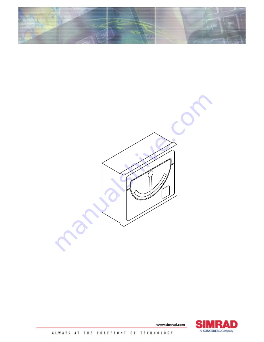
background image

INSTRUCTION MANUAL

Simrad RI35 Mk2
Rudder Angle Indicator

Summary of Contents for RI35 Mk2

Page 1: ...INSTRUCTION MANUAL Simrad RI35 Mk2 Rudder Angle Indicator ...

Page 2: ...ipment or injury to personnel The user must be familiar with the contents of the appropriate manuals before attempting to operate or work on the equipment Simrad AS disclaims any responsibility for damage or injury caused by improper installation use or maintenance of the equipment Copyright 2003 Simrad AS The information contained within this document remains the sole property of Simrad AS No par...

Page 3: ...udes a warranty card This must be filled out by the authorized dealer that performed the installation and mailed in to activate the warranty Document revisions Rev Date Written by Checked by Approved by A 101100 NG IK TR B 210601 NG IK TR C 040702 NG IK ThH D 130603 Document history Rev A Original Issue Rev B RI35 Mk2 Limiter not used with newer revisions of J3XX Rev C Connection to J50 Junction U...

Page 4: ...ion to older revision J3XX Junction units 8 Connection to J45A J45S Junction Units 9 Connection to J101A J200S Junction Units 10 3 2 Use of NMEA 11 3 3 Panel mounting 11 3 4 Bracket mounting 12 3 5 Illumination 12 3 6 Zero adjust 13 Autopilots with no rudder zero adjust 13 Autopilots with rudder zero adjust 13 Autopilots with Rudder feedback calibration 13 3 7 Reversed deflection 13 4 MAINTENANCE ...

Page 5: ...n either side of the midship s position With no signal input the pointer moves out of scale to port A front panel key is used for illumination and setup adjustments The splash proof construction allows panel bulkhead or bracket mounting in exposed locations such as bridge wings as well as wheel house and engine room 2 TECHNICAL SPECIFICATIONS Dimensions See Figure 2 1 Weight 1 0 kg Material Epoxy ...

Page 6: ...alone Cable 20 m single twisted pair not connected Rudder Feedback Units RF300 RF300S frequency signal RF45X current or frequency signal RF100 current signal Figure 2 1 RI35 Mk2 Dimensions 3 INSTALLATION The RI35 Mk2 is designed for flush bulkhead or bracket mounting and should be positioned in a location in clear view of the helmsman When the mounting location is determined the cables should be c...

Page 7: ...MEA N MEA Figure 3 1 RI35 Mk2 RF45X Stand alone wiring diagram Note If more than one indicator is needed the other indicators must be connected via the NMEA ports Max 5 indicators 1 4 RF300 Rudder Feedback Unit Non polarized colour independant FRE Q SU PPL Y C UR R RF300 RUDDER FEEDBACK UNIT RI35 Mk2 RUDDER ANGLE INDICATOR RI35 Mk2 RUDDER ANGLE INDICATOR FRE Q SU PPL Y C UR R SUPPLY VOLTAGE 12 24V...

Page 8: ...r J3XX Junction Units that have Main PCB rev E onwards For older J3XX versions see page 8 The interconnection cables are screened and the screen should be grounded in the autopilot junction unit See Figure 3 3 through Figure 3 9 for connections to the different autopilot junction units Figure 3 3 RI35 Mk2 J50 J3XX Wiring diagram dependent of autopilot function ...

Page 9: ...Instruction manual 20220919D 7 Figure 3 4 RI35 Mk2 J50 J3XX independent function of autopilot This connection gives you a full functioning indicator also with the autopilot switched off ...

Page 10: ...e autopilot junction unit Note If the J3XX junction unit has 24V supply Vbat the RI35 Mk2 Limiter part no 22084990 must be connected to RF as shown in Figure 3 5 Non polarized colour independant JUNCTION UNIT MAIN PCB Rudder Feedb RF RF FRE Q SU PPL Y C UR R RF300 RUDDER FEEDBACK UNIT RI35 Mk2 RUDDER ANGLE INDICATOR RI35 Mk2 RUDDER ANGLE INDICATOR FRE Q SU PPL Y C UR R Vbat DATABOX NMEA Input1 N M...

Page 11: ...it is connected to J45A or J45S junction units the S1 plug in strap on the RF45X PCB must be set to position AP45 Non polarized colour independant J45A JUNCTION UNIT RF45X RUDDER FEEDBACK UNIT 12 11 10 G N D R U D D E R F B I P O U T B L U E G R E E N R E D FREQ SUPPLY CURR RI35 Mk2 RUDDER ANGLE INDICATOR SUPPLY VOLTAGE 12 24V RI35 Mk2 RUDDER ANGLE INDICATOR FREQ SUPPLY CURR NMEA NMEA Figure 3 7 R...

Page 12: ... common GND Connection to J101A J200S Junction Units J101A J200S JUNCTION UNIT RF100 RUDDER FEEDBACK UNIT RI35 Mk2 RUDDER ANGLE INDICATOR SUPPLY VOLTAGE 12 24V DC 12 11 10 G N D R U D D E R F B I P O U T B L U E G R E E N R E D 1 1 F RE Q SU PPL Y C UR R G R E E N Non polarized colour independant Use a separate terminal for this connection N MEA RI35 Mk2 RUDDER ANGLE INDICATOR F RE Q SU PPL Y C UR...

Page 13: ...ta RSA 20Hz is recommended Max 5 indicators 1 4 FRE Q SU PPL Y C UR R RF45X RUDDER FEEDBACK UNIT RI35 Mk2 RUDDER ANGLE INDICATOR SUPPLY VOLTAGE 12 24VDC RI35 Mk2 RUDDER ANGLE INDICATOR G R E E N R E D B L U E FRE Q SU PPL Y C UR R N MEA N MEA RI35 Mk2 RUDDER ANGLE INDICATOR F RE Q SU PPL Y C UR R N MEA Figure 3 10 RI35 Mk2 NMEA connection 3 3 Panel mounting Make a panel cut out of 126 x 102 mm Use...

Page 14: ...ting surface Remove the RI35 Mk2 drill the 4 mounting holes in the mounting surface Unbolt the temporarily fitted bracket halves and secure them to the mounting surface using the self tapping screws Assemble the complete bracket again and adjust the RI35 Mk2 to best viewing angle and tighten up the mounting bracket bolts Figure 3 12 RI35 Mk2 Bracket mounting 3 5 Illumination Internal LED s illumin...

Page 15: ... the rudder amidships using the RI35 Mk2 as reference and then zero adjust the autopilot Autopilots with Rudder feedback calibration If the RI35 Mk2 has a different deflection compared to the readout on the autopilot i e hard over stbd shows 40 on the autopilot but only 30 on RI35 Mk2 it is most probably caused by the Feedback calibration adjustment made in the autopilot To make them read the same...

Page 16: ...he automatic self test A short beep after the long start up beep indicates that you have entered self test mode successfully The self test will now run the pointer to 45 deg port and 45 deg starboard then 20 deg port 20 deg starboard In 1 second intervals the self test will set all 3 illumination levels When self test is finished the RI35 Mk2 will run pointer to 0 deg and stay there until power is...

Page 17: ...B 22083968 RI35 Mk2 Front Panel 22084016 RI35 Mk2 Front Housing 22083992 RI35 Mk2 Back Cover 44164135 Blind plug 44140796 Cable gland 44141174 Seal o ring 44140812 Screw 3x7 mm 44148898 Screw M4x12 22083307 Spacer 44163699 Plug in terminal 2 pole 44119154 Diode LED Green HLMP 1540 44138725 Dimmer Switch B3F 22084990 RI35 Mk2 Limiter for 24VDC and separate supply with old J3XX junction unit ...

Page 18: ...Simrad RI35 Mk2 Rudder Angle Indicator 16 20220919D ...

Reviews: