


Rev. 0.3 9/08
Copyright © 2008 by Silicon Laboratories
ToolStick Programming Adapter
To o l St i c k P r o g r a m m i n g A d a p t e r
T
O O L
S
T I C K
P
R O G R A M M I N G
A
D A P T E R
U
S E R
’
S
G
U I D E
1. Handling Recommendations
The ToolStick Base Adapter and daughter cards are distributed without any protective plastics. To prevent damage
to the devices or the host PC, please take into consideration the following recommendations when using the
ToolStick:
Never connect or disconnect a daughter card to or from the ToolStick Base Adapter while the Base Adapter is
connected to a PC.
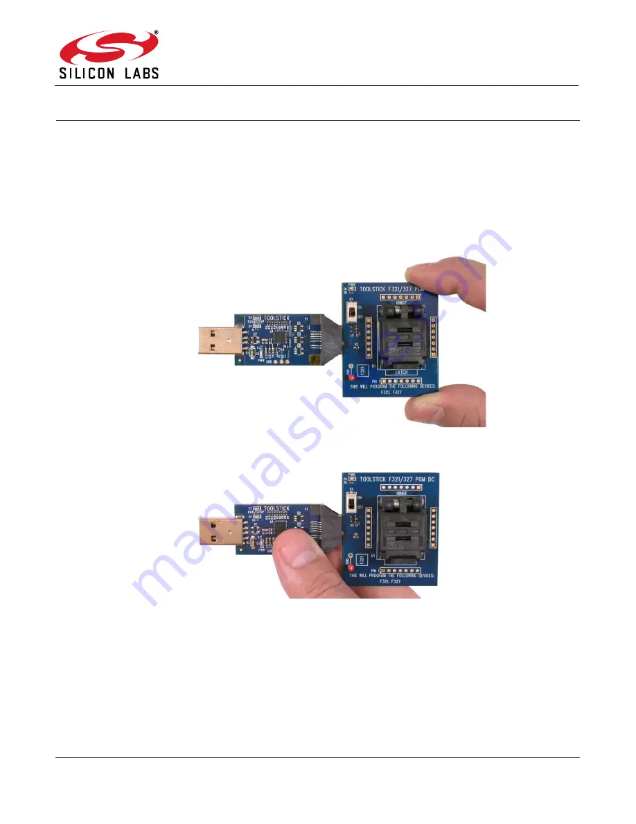
Always connect and disconnect the ToolStick Base Adapter from the PC by holding the edges of the board.
Figure 1. Proper Method of Holding the ToolStick
Figure 2. Improper Method of Holding the ToolStick
Avoid directly touching any of the components other than the plastic connector or the socket.
2. Kit Contents
The ToolStick Programming Adapter package contains the following items:
ToolStick Base Adapter
ToolStick Programming Adapter Daughter Card
USB extension cable


