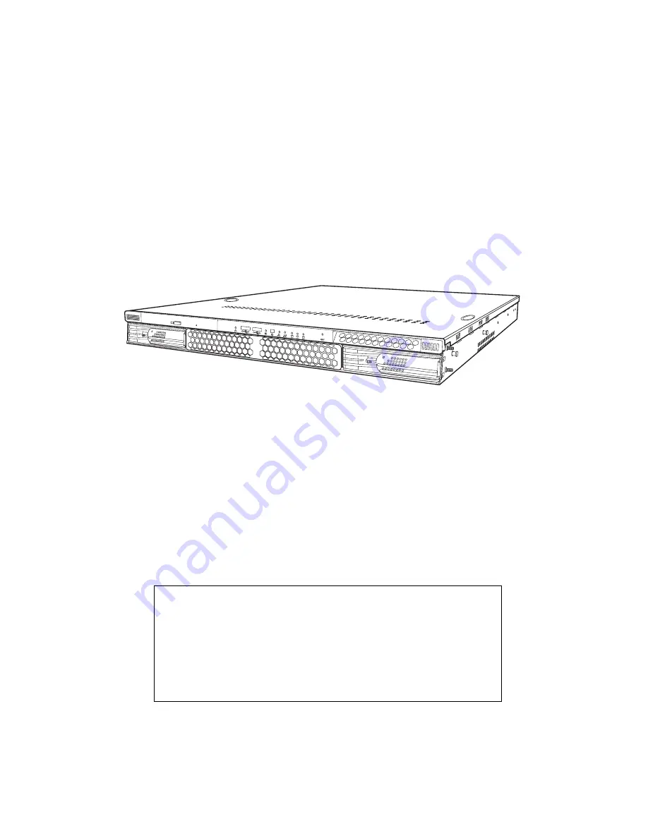
background image

Transport GX21

B5350

User’s Manual

WARNING!

This product should be serviced only by qualified service 
engineers. Do not remove the chassis cover or attempt to 
service this product unless you are qualified to do so. Once 
the chassis cover is removed, there is a risk of electric 
shock that could lead to serious injury or death.

Summary of Contents for Transport GX21 B5350

Page 1: ...d be serviced only by qualified service engineers Do not remove the chassis cover or attempt to service this product unless you are qualified to do so Once the chassis cover is removed there is a risk...

Page 2: ...tions and or specifications at any time without notice In no event will TYAN be held liable for any direct or indirect incidental or consequential damage loss of use loss of data or other malady resul...

Page 3: ...t into an outlet on a circuit different from that of the receiver Consult the dealer on an experienced radio television technician for help Notice for Canada This apparatus complies with the Class B l...

Page 4: ...list describes the external components gives tables of key components and provides block diagrams of the system Chapter 2 Covers procedures on installing the CPUs memory modules optional PCI card and...

Page 5: ...pose of this pin If your outlet does not support this type of plug contact an electrician to replace the obsolete outlet Do not place anything on the power cord Place the power cord where it will not...

Page 6: ...mponents 11 Removing the chassis cover 11 Installing CPUs 12 Installing memory 15 Installing a PCI card 16 Installing a hard drive 20 Installing an external S ATA hard drive 20 Rack mounting 23 Replac...

Page 7: ...and reliability The add on S ATA storage controller provides great flexibility and is combined with Gigabit Ethernet ports to provide powerful computing capacity and optimal I O bandwidth for the mos...

Page 8: ...M1027 hardware monitoring IC Motherboard Tyan Tiger i7510 S5350 mother board ATX form factor Phoenix BIOS on 8 Mb LPC flash ROM Memory Dual channels 8 DIMM sockets Support for up to 6 DDR333 or 8 DDR2...

Page 9: ...ROM drive pre installed Slim FDD adapter S ATA backplane and holding bracket pre installed LED control board pre installed 64 bit riser card pre installed EPS 12V 500W PSU pre installed 15 500 rpm co...

Page 10: ...External Input J33 CMOS Clear Pin 1 2 Close Normal Default Pin 2 3 Close Clear CMOS J34 Front USB Header USB2 via an optional cable J36 COM2 port via a cable J43 PCI X B PC12 Speed 1 2 Close 100MHz De...

Page 11: ...the box Open the box carefully and ensure that all components are present and undamaged The product should arrive pack aged as illustrated below http www tyan com http w ww tya n com Box contents as...

Page 12: ...causing a shutdown failure OCP OVP Fan Fail Blinking Amber Power supply warning events where the power supply continues to operate high temp high power high current slow fan Blinking Green AC present...

Page 13: ...9 Power connector located underneath the cabling 3 Slim CD ROM drive 10 Memory slots 4 Fan bracket 11 EPS 12V 500W power supply 5 IDE connector located under neath the fan bracket 12 Processor sockets...

Page 14: ...V VRD DDR PWR 1 25V VRD DDR TERM SO DIMM 200 CK409B CLOCK SYNTH DRVR DB800 BUFFER FANx CPU_FAN1 CPU_FAN2 CHASSIS_FAN LPC BUS LPC BUS PCI 32 33MHz 8MB DISPLAY MEMORY CRT CONN PCI 32 33MHz SLOTs PCI X S...

Page 15: ...d cause malfunc tions Use containers to keep small components separated Putting all small components in separate containers prevents them from becoming lost Adequate lighting and proper tools can prev...

Page 16: ...e Avoid touching motherboard components IC chips connectors memory modules and leads The motherboard is pre installed in the system When removing the motherboard always place it on a grounded anti sta...

Page 17: ...odules and PCI card 2 2 1 Removing the chassis cover Follow these instructions to remove the Transport GX21 B5350 chassis cover This step is required before any other procedures in this chapter can be...

Page 18: ...t GX21 B5350 system This section applies to all models 1 Remove the chassis cover as described in section 2 2 1 Removing the chassis cover 2 Locate the CPU sockets on the motherboard as shown below 3...

Page 19: ...ace the CPU in the CPU socket ensuring that pin 1 is located as shown in the following illustration 6 Press the CPU locking lever back down to secure the CPU in the socket 7 Repeat steps three to six...

Page 20: ...Installing motherboard components 14 Chapter 2 Setting up 9 Tighten the four screws to secure the heatsinks in place as shown below Note CPU heatsinks must be removed to install or remove memory modu...

Page 21: ...Removing the chassis cover 2 Locate the memory slots on the motherboard 3 Press the memory slot locking levers in the direction of the arrows as shown below Note It is not possible to move the mem ory...

Page 22: ...cking levers are firmly in place and that the memory module is properly seated in the slot 2 2 4 Installing a PCI card Follow the instructions in this section to install a PCI card in your Transport G...

Page 23: ...2 2 Installing motherboard components Chapter 2 Setting up 17 3 Remove the screw securing the PCI faceplate to the chassis 4 Slide the PCI card clamp out as shown 5 Slide the dust cover out...

Page 24: ...he PCI card into place in the slot on the riser card Ensure that the card is seated properly in the slot on the riser card and that the riser card is properly seated in its slot on the motherboard 7 R...

Page 25: ...2 2 Installing motherboard components Chapter 2 Setting up 19 8 Insert the screw to secure the PCI card to the chassis...

Page 26: ...2 3 1 Installing an external S ATA hard drive Follow these instructions to install an external S ATA hard drive in your system 1 Remove the chassis cover as described in section 2 2 1 Removing the ch...

Page 27: ...tting up 21 4 Place a S ATA drive in the drive bay Note If you are replacing an existing HDD you will need to remove the four screws that secure it in the drive bay and remove it 5 Insert four screws...

Page 28: ...2 3 Installing a hard drive 22 Chapter 2 Setting up 6 Reinsert the drive bay into the chassis Ensure that the rear connector of the new drive is firmly seated in the backplane...

Page 29: ...in a rack but it is preferable to install the device in a fully operational condition 1 Screw the mounting ears to the Transport GX21 as shown using 4 screws from the supplied nuts screws and washers...

Page 30: ...the Transport GX21 as shown You will need 3 short silver colored screws from the supplied nuts screws and washers kit for each rail 5 Return the sliding rails to their shortest position Note When full...

Page 31: ...unit 7 Accurately measure the depth of your rack and adjust the rear brackets accordingly 8 When all brackets are positioned correctly tighten them 9 Lift the unit into place in the rack and screw it...

Page 32: ...2 4 Rack mounting 26 Chapter 2 Setting up...

Page 33: ...replacement for two 1 port S ATA backplanes Before you attempt to replace any components make sure you have read section 2 1 Before you begin in chapter 2 which describes the precautions you need to t...

Page 34: ...herboard components 28 Chapter 3 Replacing installed components 1 Disconnect power cables Note There are two air ducts leading from the fans covering the CPUs 2 Disconnect CD ROM drive cable and S ATA...

Page 35: ...alled components 29 Note If there is an FDD installed you will have to disconnect those cables too before you can remove the motherboard 3 Disconnect front panel LED and USB connectors 4 Remove fan an...

Page 36: ...the motherboard from your Transport GX21 B5350 Note Before removing the motherboard you must remove all cable connections to the motherboard See section 3 2 1 Disconnect ing all motherboard cables fo...

Page 37: ...motherboard from the chassis 3 3 Replacing the CD ROM drive This section describes how to remove and replace the CD ROM drive in your Transport GX21 B5350 system 1 Remove the chassis cover as describ...

Page 38: ...ter 3 Replacing installed components 4 Remove the two screws that secure the CD ROM back plane to the CD ROM drive 5 Lift the drive from the chassis 3 4 Replacing the LED control board Follow these in...

Page 39: ...ecure the LED control panel to the chassis and lift the board free of the chassis 3 5 Replacing the storage backplane This section describes how to replace the S ATA backplane on your Transport GX21 B...

Page 40: ...moving the backplane See 3 2 Replacing mother board components for details on how to do this 3 Remove the three screws that secure the S ATA back plane bracket to the chassis 4 Remove the S ATA backpl...

Page 41: ...talled components 35 3 5 0 1 S ATA backplane features Note B5350G21S2H is shipped with two 1 port S ATA backplanes to support 2 hot swap S ATA hard disk drives J3 serial ATA 7 pin connector JP2 HDD LE...

Page 42: ...tion 2 2 1 Removing the chassis cover 2 Disconnect power cables from the motherboard back planes FDD CD ROM drive and fans See 2 3 Installing a hard drive 3 2 1 Disconnecting all motherboard cables se...

Page 43: ...em 1 Remove the chassis cover as described in section 2 2 1 Removing the chassis cover 2 Remove the PCI retention bar Note You may need to cut the cable ties that secure the fan power cables before at...

Page 44: ...fan bracket Note The Transport GX21 B5350 uses two different types of cooling fans which operate at different speeds The fan installed nearest the power supply has a peak speed of 15 000 rpm The othe...

Page 45: ...ction of the appendix describes the various BIOS settings that can be used to configure your system BIOS setup utility With the BIOS setup utility you can modify BIOS settings and control the features...

Page 46: ...sor to the required sub menu and press Enter BIOS menu bar The menu bar at the top of the window lists the following selections Menu bar selections Main Configure basic system setup options Advanced C...

Page 47: ...can be changed The right frame displays the key legend Above the key leg end is an area reserved for a text message When an option is selected in the left frame it is highlighted in white Often a tex...

Page 48: ...date Legacy Diskette A NONE 360 K 5 25 in 1 2 M 5 25in 720K 3 5 in 1 44 M 3 5 in 2 88 3 5 in Set the floppy drive type IDE Channel submenu Set IDE drive configuration Memory Cache submenu Set memory...

Page 49: ...Appendix 43 IDE channel submenus You can use this screen to change IDE Configuration Set tings...

Page 50: ...of disk Multi Sector Transfers Disabled 2 sectors 4 sectors 8 sectors 16 sectors Set number of sectors per block for multiple sector transfers LBA Mode Control Enabled Disabled Set LBA on or off 32 b...

Page 51: ...reen to change memory caching settings Feature Option Description Cache System BIOS area NULL Write Protect Cache system BIOS ROM shadowing must be enabled Cache Video BIOS area NULL Write Protect Cac...

Page 52: ...oppy disk at POST on or off Summary Screen Enabled Disabled Set a summary of BIOS settings at POST on or off Quiet Boot Enabled Disabled Set the OEM logo during boot up on or off QuickBoot Mode Enable...

Page 53: ...000 Set the installed operating system Note Incorrect settings may cause the system to behave unpredictably Reset Configuration Data Yes No Force BIOS to discard old config uration and re detect hardw...

Page 54: ...Advanced Chipset Con trol submenu Configures USB controller and legacy device support Advanced Processor Options submenu Set advanced processor options I O Device Configuration submenu Configure I O...

Page 55: ...Appendix 49 Hardware monitor You can use this screen to change critical system settings...

Page 56: ...2 submenu Spectrum Spread Force Compliance Mode Entry Enabled Disabled Set PCI E compliance mode DRAM Data Integ rity Mode Disabled 72 bit ECC 144 bit ECC Auto Set ECC mode for ECC memory mod ules EC...

Page 57: ...en to control USB Memory Remap Function Enabled Disabled Remap BIOS memory to above 1 MB BIOS cannot be shadowed when this is enabled Feature Option Description USB Device 29 Function Enabled Disabled...

Page 58: ...se these screens to set options for the integrated LANs Feature Option Description PCI E port Auto Disabled Enabled Force PCI Express v1 0 Com patibility Mode Set PCI E compatibility mode Option ROM S...

Page 59: ...Enabled Disabled Enable Hyper Threading only if supported by processor Thermal Manage ment 2 Enabled Disabled Prevent damage to the CPUs by slowing the processor Full speed resumes when a stable tempe...

Page 60: ...Disabled Turn serial port B on or off Base I O address 3F8 2F8 3E8 2E8 Set the base I O address for serial port B Interrupt IRQ3 IRQ4 Set the interrupt for serial port B Mode Normal IrDA ASK IR Set th...

Page 61: ...Appendix 55 DMA Channel DMA 1 DMA 3 Set the DMA channel for the par allel port Floppy disk con troller Enabled Disabled Set the Floppy Disk on or off Feature Option Description...

Page 62: ...reen to set DMI event logging options Feature Option Description Event Logging Enabled Disabled Set DMA Logging on or off ECC Event Logging Enabled Disabled Set ECC Logging on or off Clear all DMI eve...

Page 63: ...or external console use Baud Rate 300 1200 2400 9600 19 2K 38 4K 57 6K 115 2K Set the baud rate for the COM port Console Type VT100 VT100 8bit PC ANSI 7bit PC ANSI VT100 VT UTF8 NULL Set the console t...

Page 64: ...og Timeout Set the time for BIOS to stop the Watchdog Timer after a reset has occurs BIOS Boot Timeout Set time for BIOS to boot before the system is reset OS Boot Timeout Time for OS to boot before s...

Page 65: ...ure Option Description Set Supervisor Password Set the supervisor password which restricts access to the BIOS Set User Password Set user password Password on boot Set system to ask for password at sta...

Page 66: ...havior On Off Wake Sleep Set power button to switch power on and off or sleep and wake up After power Failure Enabled Disabled Set the system to return to previous state or stay powered off after a po...

Page 67: ...Appendix 61 Boot menu You can use this screen to set boot up options...

Page 68: ...re Option Description Exit Saving Changes Save changes made and exit BIOS Exit Discarding Changes Discard changes made and exit BIOS Load Setup Defaults Restore all BIOS settings to factory defaults D...

Page 69: ...ise for service If any problems occur during the product s warranty period consult your system vendor or distributor before contacting TYAN The warranty covers normal customer use of the product The w...

Page 70: ...64 Appendix...

Reviews: