background image

R

R

R

E

E

E

P

P

P

A

A

A

I

I

I

R

R

R


I

I

I

N

N

N

S

S

S

T

T

T

R

R

R

U

U

U

C

C

C

T

T

T

I

I

I

O

O

O

N

N

N

S

S

S


FX-C 

1


SAFETY ........................................................ 3


4.5


L-Gasket ............................................................................ 12


4.6


Outer Tub .......................................................................... 12


1.1


Safety instructions.............................................................. 3


4.7


Drum .................................................................................. 12


1.2


Safety at work...................................................................... 4


4.8


Heater ................................................................................ 13


2


INSTALLATION ............................................ 5


4.9


NTC .................................................................................... 13


4.10


Motor / motor actuation.................................................... 14


2.1


Aligning the appliance........................................................ 5


4.11


Magnet-valves................................................................... 15


2.2


Water supply ....................................................................... 5


4.12


Hot water magnet-valve (optional) .................................. 15


2.3


Water outlet ......................................................................... 6


4.13


Water flow ......................................................................... 16


2.4


Electrical connection .......................................................... 6


4.14


Drain Pump ....................................................................... 16


3


OPERATION ................................................. 7


4.15


Pressure switch ................................................................ 16


3.1


Operation in general ........................................................... 7


5


FUNCTIONS................................................17


3.2


Programme selector ........................................................... 7


5.1


Load detection function ................................................... 17


3.3


Selection Buttons ............................................................... 7


5.2


Foam detection function .................................................. 17


3.4


“Start” button (optional)..................................................... 7


6


REPAIR .......................................................18


3.5


“Start/Pause” button (optional) ......................................... 7


3.6


LEDs displays ..................................................................... 8


6.1


Diagnosis / Repair aids .................................................... 18


3.7


“Extra Wash” / “Super Wash” button................................ 8


6.2


Cleaning the drain pump.................................................. 19


3.8


Audible Signal ..................................................................... 8


6.3


Top cover .......................................................................... 20


3.9


Child Safety device (optional)............................................ 9


6.4


Front panel ........................................................................ 21


4


COMPONENTS........................................... 10


6.5


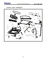
Control Panel .................................................................... 23


6.6


Disassembly of the control module ................................ 24


4.1


Top cover........................................................................... 10


6.7


Removing the door lock................................................... 25


4.2


Knob................................................................................... 10


6.8


Assembly the door lock ................................................... 25


4.3


Control Module.................................................................. 11


6.9


Tub Disassembly .............................................................. 26


4.4


Door lock ........................................................................... 11


6.10


Tub assembly.................................................................... 27


209_58300000115677_ara_en_f.doc – 26.03.08 

Seite 1 von 34 

Summary of Contents for FX-C

Page 1: ...eneral 7 5 FUNCTIONS 17 3 2 Programme selector 7 5 1 Load detection function 17 3 3 Selection Buttons 7 5 2 Foam detection function 17 3 4 Start button optional 7 6 REPAIR 18 3 5 Start Pause button optional 7 3 6 LEDs displays 8 6 1 Diagnosis Repair aids 18 3 7 Extra Wash Super Wash button 8 6 2 Cleaning the drain pump 19 3 8 Audible Signal 8 6 3 Top cover 20 3 9 Child Safety device optional 9 6 4...

Page 2: ...Drain Pump 30 7 FAULT DIAGNOSTICS 31 7 1 Appliance stability 31 7 2 Washing results 31 7 3 Time skips 31 7 4 Controller 32 7 5 Small clothes get caught Clothes breakage 33 8 TECHNICAL SPECIFICATIONS 34 8 1 Consumption rates 34 209_58300000115677_ara_en_f doc 26 03 08 Seite 2 von 34 ...

Page 3: ...uit breaker 4 The protective conductor resistance must never exceed the values specified in the standard 5 The protective conductor is crucial for personal safety and appliance function When repairs are complete perform a test in accordance with VDE 0701 or the corresponding national regulations 6 Also check for leaks Warning Comply with the following instructions When performing a test in accorda...

Page 4: ...y at work Potential hazards Keep always your back straight 1 2 1 Pull the appliance forwards Wrong posture Right posture 1 2 2 Push the appliance backwards 209_58300000115677_ara_en_f doc 26 03 08 Seite 4 von 34 ...

Page 5: ...he water connection 3 4 inch requires a conventional water line with a water pressure of at least 1 bar 1 at when the tap is turned on the water flow rate must be more than 8 l min If the water pressure is more than 10 bar 10 at a pressure reducing valve must be installed 2 2 1 Warm water version optional The warm water appliances feature 2 valves The warm water connection is red and may be connec...

Page 6: ...et mat no 432060 2 4 Electrical connection Connect the appliance to a correctly installed earthed socket only Comply with the specifications on the rating plate Fuse 15 A A 3 m long connection cable incl earthed plug is available from customer service mat no 481580 A approx 100 cm D approx 90 cm B approx 145 cm E max 100 cm C approx 135 cm 209_58300000115677_ara_en_f doc 26 03 08 Seite 6 von 34 ...

Page 7: ...ion buttons Spin Speed With the left button under the display you can select the rotation speed Even without spin drying can be selected Then an intermediate spin drying cycle runs but at the end of the program the laundry is left in the last rinsing water Temperature With the middle button under the display can be selected the temperature Start time preselection With the right button under the di...

Page 8: ...Turn the programme selector to Ein Aus Press the Start Pause button and turn the programme selector to Koch Buntwäsche Hold the Start Pause button down until the signal is heard The selected adjustment is memorised Turn the programme selector one more to Ein Aus When the extra funtions start a long signal is heard When an extra function is turned off the audible signal is a short one This funtion ...

Page 9: ... the audible signal is activated and deactivated Release the button when the signal goes out The alarm of the Start Pause button and programme status is deactivated 3 9 Child Safety device optional 3 9 1 Turning on the child safety Press the Start Pause button The programme starts Press the Start Pause button and hold it down approximately 4 seconds until the symbol appears after which Paus appear...

Page 10: ...necessary for the right function of the appliance cause of it has mechanic functions In case of remove the original top cover cause of a little niche is avaliable a VDE top cover mat no 472560 4 2 Knob The knob and the axis are only one part 209_58300000115677_ara_en_f doc 26 03 08 Seite 10 von 34 ...

Page 11: ...main characteristic is that the variant coding is made through the programe selector and the buttons That means that all the modules are able to be coded The frecuency window of the module is 45 76 Hz Electrostatic sensitive devices Please observe handling regulations 4 4 Door lock The door lock is electromechanic and it consist in a PTC which is heated when it receives tension and the inside wax ...

Page 12: ...et the grease resistant gasket is Mat no 360000 4 6 Outer Tub The tub consists of two talcum shells until 1200 rpm and two glass fibre reinforced plastic shells for 1400 rpm These shells are screwed and clipped 4 7 Drum The spare part for the drum includes the support of the drum The drum for the appliances of 1400 rpm is reinforced with a metal band 209_58300000115677_ara_en_f doc 26 03 08 Seite ...

Page 13: ...e NTC operating range is between 5 C and 103 C If the NTC value is outside the operating range e g interruption or short circuit the programme continues cold without an error display The test programme displays NTC short circuit or NTC interruption The NTC is inserted into the heating flange and is sealed with the heater seal The NTC can be removed after desconnecting the heater Temperature in C R...

Page 14: ... with empty drum Wool 27 min 1 5 Wet 35 min 1 3 Rinse 56 min 1 3 Wash 56 min 1 3 Spin see table 2 5 Teoric speed Max Speed 1400 1360 1300 1300 1200 1140 1100 1100 1000 900 960 800 700 750 600 600 500 500 Measurement speed unbalanced load 100 min 1 1 If an unbalanced load is detected the speed is reduced in the final spin cycle as follows Start up attemps Appliance min 1 1 5 6 8 9 15 15 1400 nmax m...

Page 15: ...220 240 V Frecuency 50 60 Hz Power 6 W Maximal flow 11 l min 4 12 Hot water magnet valve optional The appliances with hot water inlet include an additional magnet valve for the hot water inlet Technical Data Voltage 220 240 V Frecueny 50 60 Hz Power 6 W Maximal flow 10 1 l min 209_58300000115677_ara_en_f doc 26 03 08 Seite 15 von 34 ...

Page 16: ...ter tank has been omitted and it has been included in the drain pipe 4 14 Drain Pump 4 14 1 Function The detergent solution pump features a thermal protection device 4 14 2 Technical specifications Nominal voltage 230 240 V Frequency 50 Hz Resistance 170 7 Ω Delivery head 1 0 m Delivery rate 18 l min 4 15 Pressure switch The pressure switch has 2 levels Level I Heating level Aprox 26 36 mm from th...

Page 17: ... 65 seg full load it depends on the programm N Nivel Points of load detection function Water supply times t1 t2 t3 t4 5 2 Foam detection function If during the rinse is reached the level I of the pressure switch the module understand that there is foam in the drum cause of over dosage of detergent In this case the spin will be stopped will be drained and there will be an extra rinse 209_5830000011...

Page 18: ...river Screwdriver of 85 mm to disassembly the screw of the front panel mat no 460621 6 1 5 Unbalanced load detection The termination of the spin cycle by the unbalanced load scan can be reset with the aid of a water filled thermal bottle The thermal bottle with contents must weight at least 800 g 6 1 6 Plastic side cutters Plastic side cutters mat no 340701 for repairs to the outer tub 6 1 7 Drill...

Page 19: ...iance has a cover in the front panel This cover is clipped After removing this cover we can access to the filter of the pump Caution When the cover of the filter is opened the water can fall down on the floor 209_58300000115677_ara_en_f doc 26 03 08 Seite 19 von 34 ...

Page 20: ...ove The fixation pivots are included in the top cover 6 3 2 Assembly of the top cover VDE Remove othe original top cover Install the plastic supports supplied with the kit in the fixation points of the original top cover Put the new VDE top cover and screw 209_58300000115677_ara_en_f doc 26 03 08 Seite 20 von 34 ...

Page 21: ...ce throw the rear part leaving a place in the lower part of 10 cm With the screwer mat no 460621 unscrew the two screws A in the base and leave the machine in the floor Remove the external ring of the gasket Remove the door lock by pressing the points C Pull up of the lower part of the front panel there are two pivots A in the middle of the front panel and remove C Pressure points for removing the...

Page 22: ...6 4 2 Assembly Introduce the two upper pivots B Fix the two lower pivots A and Screw the two lower screws C 209_58300000115677_ara_en_f doc 26 03 08 Seite 22 von 34 ...

Page 23: ...etail of the hook 6 5 2 Disassembly of the control panel Unscrew the fixation screws Loose the hook B in the right side Slide the control panel to the right and remove A Detail of the hooks 6 5 3 Assembly of the control panel Insert the hooks A and B in the housing Screw the three screws 209_58300000115677_ara_en_f doc 26 03 08 Seite 23 von 34 ...

Page 24: ...o the control panel Remove the electric connections Atenttion Place in right place the rubber transmission between the buttons and the module In other case it is possible that the LEDs will be not right seen and the buttons don t work 209_58300000115677_ara_en_f doc 26 03 08 Seite 24 von 34 ...

Page 25: ...from inside Press with the pliers in the both fixation points A Turn the rear part of the door lock to the inside 6 8 Assembly the door lock First insert the slot in the hole of the front panel Press until the lock will be fixed 209_58300000115677_ara_en_f doc 26 03 08 Seite 25 von 34 ...

Page 26: ...n the outer tub breaks please use the kit mat no 17 4842 To reduce the weight dismantle the motor jacket weight and front weight Loosen the damper on the base plate Lift the complete tub out of the washing machine housing Remove plastic clips with special side cutters mat no 340701 Dismantle the tub Carry out repairs remove foreign objects replace bearings 209_58300000115677_ara_en_f doc 26 03 08 ...

Page 27: ...6 10 Tub assembly Insert new seal Re assemble tub and screw together with 10 new screws Mat Nr 483764 209_58300000115677_ara_en_f doc 26 03 08 Seite 27 von 34 ...

Page 28: ...he dampers can be replaced without removing the outer tub Drill plug in spindle head 30 mm deep Press out the plug in spindle towards the rear 6 11 2 Assembly Insert bushings into the eye of the damper Insert damper into the support on the outer tub From the rear insert a screw with the flattened washer Insert screw with centring washer and secure with the hex lock nut 209_58300000115677_ara_en_f ...

Page 29: ... always 4 supports Desmontaje Remove the rear cover Remove the self tensioning belt Remove the two bolts A Remove the front panel Pull out the motor towards the rear Sharp edges Wear protective gloves Please use the assembly mat no 174842 A if the plastic holder for the motor cable harness breaks 209_58300000115677_ara_en_f doc 26 03 08 Seite 29 von 34 ...

Page 30: ...isassembly of the Drain Pump Remove the front panel Loosen and remove the hoses Remove the electrical connections Loosen the screw A Remove drain pump 209_58300000115677_ara_en_f doc 26 03 08 Seite 30 von 34 ...

Page 31: ...uctions 58300000002975 Does not heat up or insufficiently Test heating circuit with test programme if required replace defective component Does not wash clean or not clean enough allergy sufferer Detergent load programme selection dosage See general repair instructions 58300000002975 Fault details Cause Remedial action Running times and time skips Adjust the control to the influencing variables fo...

Page 32: ...h the selected temperature in 105 minutes and go to the next step Do the test program and test the heating Pumping defect The pressure switch doesn t reach level N1 in 56 minutes and go to the next step Do the test program and test the pumping Module is not functioning Electrical component has a short circuit or earth fault Remove the component from the module if the module functions replace the r...

Page 33: ...akage Fault details Cause Remedial action Small clothes get caught or clothes breakage The gap between the drum and the gasket is too big Change the L gasket by a J gasket mat no 354135 209_58300000115677_ara_en_f doc 26 03 08 Seite 33 von 34 ...

Page 34: ...30ºC 2 kg 0 30 55 44 Wool 30 C 2 kg 0 20 35 61 Test programmes in compliance with EN 60 456 1999 and IEC 60456 Ed 3 1998 02 The consumption values and running times will deviate from the specified values depending on the water pressure softness inlet temperature room temperature type of laundry quantity and selected additional functions The consumption values refer to series start up The running t...

Reviews: