Siemens CP 343-5, Manual
The Siemens CP 343-5 is a cutting-edge communication processor that facilitates seamless integration of network data in your industrial automation systems. Its user manual, available for free download at manualshive.com, provides comprehensive guidance on setup, configuration, and operation, ensuring optimal performance and productivity for your operations.
Share
Download


Reviews:
No comments
Related manuals for CP 343-5

CP 31
Brand: Rane Pages: 4

EK-Vector Radeon RX5700 + XT Backplate
Brand: ekwb Pages: 7

Speedway Revolution
Brand: impinj Pages: 60

EGO AE120
Brand: Aurora Pages: 6

VDX-6354RD
Brand: ICOP Technology Pages: 42

B078-001-USB
Brand: Tripp Lite Pages: 2

8314/2H
Brand: ebm-papst Pages: 6

D3G160-BD05-02
Brand: ebm-papst Pages: 12

IRONCLAD TS-1
Brand: Garner Pages: 13

HORIZON Random Access Memory
Brand: NorthStar Pages: 69

PROFIBUS-DP PDP003Z
Brand: Toshiba Pages: 38

nv-pack JTLI41
Brand: Toshiba Pages: 58

nv-pack Series
Brand: Toshiba Pages: 95

RemotEye III
Brand: Toshiba Pages: 167

PDG-DET100L - SXGA+ DLP Projector
Brand: Sanyo Pages: 1
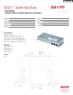
ECO-i SHA-LN16UAB
Brand: Sanyo Pages: 1

PDG-DET100L - SXGA+ DLP Projector
Brand: Sanyo Pages: 92

PDG-DET100L - SXGA+ DLP Projector
Brand: Sanyo Pages: 232


