Siemens 3AH47 series, Operating Instructions Manual
The Siemens 3AH47 series, a technologically advanced electrical power switching system, comes with a comprehensive Operating Instructions Manual. This user-friendly manual provides step-by-step guidance for seamless operation. Easily accessible for free download from manualshive.com, empowering users with essential information to maximize the potential of these innovative Siemens products.
Share
Download


Reviews:
No comments
Related manuals for 3AH47 series

GRD9L-R
Brand: GEYA Pages: 4

AR-AUX-UR-220
Brand: IEK Pages: 2

SV 9677.100
Brand: Rittal Pages: 20
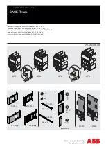
SACE Tmax XT2
Brand: ABB Pages: 5

Dynatel 2273M-iD Series
Brand: 3M Pages: 17

HI21-P5-125/160
Brand: Eaton Pages: 2

DILMS17 Series
Brand: Eaton Pages: 2

65320
Brand: Brady Pages: 3

PB6012
Brand: Powtran Pages: 19

nrg600BT08-M
Brand: Amphenol Telect Pages: 19


