SICK CLV 41 Series, Operating Instructions Manual
Introducing the SICK CLV 41 Series! Ensure seamless operation with our comprehensive Operating Instructions Manual. This essential manual is available for instant, hassle-free download - absolutely free of charge. Visit our website manualshive.com to access the user manual and unlock the full potential of your CLV 41 Series product.
Share
Download


Reviews:
No comments
Related manuals for CLV 41 Series

QuickScan L QD 2300
Brand: Datalogic Pages: 192

PowerScan PD9530
Brand: Datalogic Pages: 48

QuickScan i QD2100
Brand: Datalogic Pages: 320

PowerScan PD8530
Brand: Datalogic Pages: 160

PowerScan PD7100 Corded
Brand: Datalogic Pages: 21

PowerScan M8500
Brand: Datalogic Pages: 233

POWERSCAN 7000 2D Imager
Brand: Datalogic Pages: 28

Magellan 8500Xt
Brand: Datalogic Pages: 480

Magellan 2200VS
Brand: Datalogic Pages: 432

matrix 450N
Brand: Datalogic Pages: 175

QuickScan i QD2100
Brand: Datalogic Pages: 28
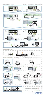
DLKpro
Brand: VDO Pages: 2

50138195
Brand: Leuze Pages: 92

Pyrus mini
Brand: TrekStor Pages: 86

35FCREADBK3
Brand: StarTech.com Pages: 2

Moby 5500
Brand: Chase Pages: 8

Touch 65 Pro
Brand: Datalogic Pages: 21

PA982
Brand: Unitech Pages: 2


