background image

E-1

Dear SHARP Customer

Welcome to the SHARP Family. We are pleased that you are now the owner of a SHARP Color
LCD Projector built for outstanding quality, reliability and performance.
Every SHARP Color LCD Projector is adjusted for a proper picture and has passed through the
most stringent quality control tests at the factory. We have prepared this OPERATION MANUAL
so that you have the ability to adjust the picture and color to your personal viewing preference.
We sincerely hope that you will be satisfied with the quality and performance of your Color LCD
Projector for many years to come.
Please read the instructions carefully, and keep them handy for future reference.

IMPORTANT
For your assistance in reporting the loss or
theft of your Color LCD Projector, please
record the Serial Number located on the rear
of the projector and retain this information.

Important Information

There are two important reasons for prompt warranty registration of your new SHARP LCD
Projector, using the REGISTRATION CARD packed with the projector.

1) WARRANTY

This is to assure that you immediately receive the full benefit of the parts, service and labor
warranty applicable to your purchase.

2) CONSUMER PRODUCT SAFETY ACT

To ensure that you will promptly receive any safety notification of inspection, modification, or
recall that SHARP may be required to give under the 1972 Consumer Product Safety Act,

PLEASE READ CAREFULLY THE IMPORTANT “LIMITED WARRANTY” CLAUSE.


 U.S.A. ONLY

WARNING: High brightness light source, do not stare into the beam of light, or view directly.

Be especially careful that children do not stare directly into the beam of light.

WARNING: TO REDUCE THE RISK OF FIRE OR ELECTRIC SHOCK, DO NOT EXPOSE

THIS PRODUCT TO RAIN OR MOISTURE.

Model No.: XG-E3500U

Serial No.:

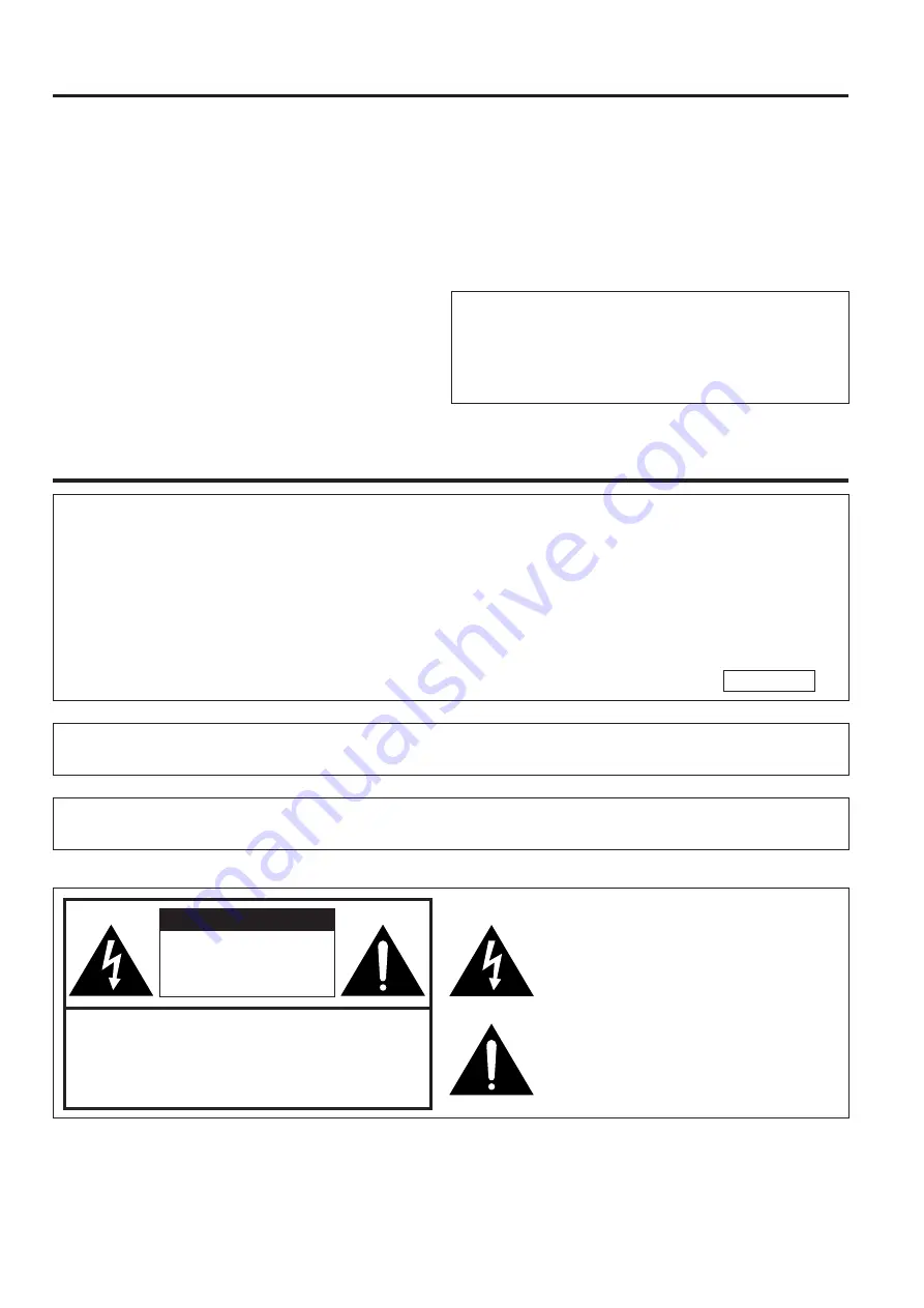
CAUTION: TO REDUCE THE RISK OF ELECTRIC SHOCK,

DO NOT REMOVE COVER.

NO USER-SERVICEABLE PARTS INSIDE.

REFER SERVICING TO QUALIFIED SERVICE

PERSONNEL.

The lightning flash with arrowhead symbol,
within an equilateral triangle, is intended to
alert the user to the presence of uninsulated
“dangerous voltage” within the product’s
enclosure that may be of sufficient
magnitude to constitute a risk or electric
shock to persons.

The exclamation point within a triangle is
intended to alert the user to the presence of
important operating and maintenance
(servicing) instructions in the literature
accompanying the product.

CAUTION

RISK OF ELECTRIC SHOCK.
DO NOT OPEN.

Summary of Contents for XG-E3500U

Page 1: ...nefit of the parts service and labor warranty applicable to your purchase 2 CONSUMER PRODUCT SAFETY ACT To ensure that you will promptly receive any safety notification of inspection modification or recall that SHARP may be required to give under the 1972 Consumer Product Safety Act PLEASE READ CAREFULLY THE IMPORTANT LIMITED WARRANTY CLAUSE U S A ONLY WARNING High brightness light source do not s...

Page 2: ...y the product manufacturer as they may cause hazards 7 Water and Moisture Do not use this product near water for example near a bathtub wash bowl kitchen sink or laundry tub in a wet basement or near a swimming pool and the like 8 Accessories Do not place this product on an unstable cart stand tripod bracket or table The product may fall causing serious injury to a child or adult and serious damag...

Page 3: ...xhibits a distinct change in performance this indicates a need for service 19 Replacement Parts When replacement parts are required be sure the service technician has used replace ment parts specified by the manufacturer or with the same characteristics as the original part Unauthorized substitutions may result in fire electric shock or other hazards 20 Safety Check Upon completion of any service ...

Page 4: ...ures Allows easy projection of large screen full color computer and video images Can be projected directly onto a video screen or white wall Lightweight convergence free system for easy installation DIRECT COMPUTER COMPATIBILITY A multi scan RGB Input accepts signals from SXGA 1 280 dots 1 024 lines compressed XGA 1 024 dots 768 lines SVGA 800 dots 600 lines VGA and Mac 1 024 dots 768 lines maximu...

Page 5: ...icator Remote sensor POWER ON OFF button Location of Controls FRONT VIEW Lamp cage cover Natural ventilation Cooling fan Intake vent SIDE AND REAR VIEW Speakers BLACK SCREEN button Notes The DC 5 V OUTPUT jack cannot supply a current of more than 0 5 A When connecting a Macintosh Series computer that outputs C SYNC connect the cable to the COMPUTER RGB 2 INPUT H SYNC input terminal Cooling fan Exh...

Page 6: ...rting the remote control turn off the MAIN POWER switch to avoid draining the batteries LEFT CLICK button SIDE VIEW Wireless Mouse Remote Control FRONT VIEW INPUT SELECT buttons Note If the MAIN POWER switch on the remote control is left on for more than 10 minutes without operation the power will automatically turn off To turn the power back on press any button on the remote control for at least ...

Page 7: ...hey may run out after a short time If so replace them with new batteries as soon as possible Remote control positioning Use the remote control as shown in the figures on the left Note The signal from the remote control can be reflected off the screen for easy operation However the effective distance of the signal may differ due to the screen material REAR VIEW Insert the side tabs into their slots...

Page 8: ...tor Functions and Operations LEFT CLICK button The LEFT CLICK button on the back of the remote control corresponds to the left button of the mouse on two button mouse systems RIGHT CLICK button The RIGHT CLICK button on the front of the remote control corresponds to the right button on two button mouse systems Note For one button mouse systems use either the LEFT CLICK or RIGHT CLICK button LASER ...

Page 9: ...he picture adjustment mode changes as shown on the left You can adjust the picture as shown on the left by pressing the ADJUSTMENT or buttons for FOCUS and ZOOM or the ADJUSTMENT or buttons for SHIFT while in ADJUST mode Note Do not attempt to adjust the lens by hand as it may damage the lens mechanism Adjust the focus until the picture on the screen is sharp The focus pattern appears on the scree...

Page 10: ...ction distance y1 0 059x 0 1175 3 28 y2 0 0371x 0 1211 3 28 x Picture size diag inches y1 Maximum projection distance ft y2 Minimum projection distance ft Note There is an error of Ⳳ4 inches Ⳳ10 cm in the formula above Maximum projection distance 96 3 ft 29 4 m 77 0 ft 23 5 m 57 7 ft 17 6 m 38 3 ft 11 7 m 28 6 ft 8 7 m 19 0 ft 5 8 m 15 1 ft 4 6 m 11 2 ft 3 4 m 7 3 ft 2 2 m Minimum projection dista...

Page 11: ...D I S P L A Y O F F O N O F F O F F S E L A D J E N D M E N U B L K S C R N D I S P I M A G E A D J R E V E R S E I N V E R T I N P U T D I S P L A Y O F F O F F O N O F F S E L A D J E N D MENU B L K S C R N D I S P I M A G E A D J R E V E R S E I N V E R T I N P U T D I S P L A Y O F F O N O N O F F S E L A D J E N D MENU 4 4 Reversed Inverted Image Mode In the IMAGE ADJ menu set the REVERSE and...

Page 12: ...of the screen Lens center Using the horizontal reverse function makes the following setups possible Example of a reversed image setup By placing a mirror normal flat type in front of the lens and using the horizontal reverse function the image reflected from the mirror can be projected onto the screen Rear projection with a rear projection screen is also possible when using the horizontal reverse ...

Page 13: ... a high mount setup A high mount setup makes projection from an elevated location possible without ceiling modifications Lens center SIDE VIEW TOP VIEW Lens center Note A polarizing screen cannot be used with this projector ON OFF POWER LAMP TEMP Inverted Labeling for Ceiling Mount When ceiling mounting the projector attach the supplied inverted label as shown ON OFF POWER LAMP TEMP ON OFF POWER L...

Page 14: ... the projector once you are sure the adjuster legs have locked in position 3 Make any minor adjustments necessary Turn the adjusters to further adjust the angle of the projector Returning the projector to its original position While holding the projector with both hands press the adjuster release and slowly lower the projector to its original position Notes Adjustable up to approximately 5 from th...

Page 15: ...onitor Note the following when using the S VIDEO INPUT terminal The S VIDEO INPUT terminal uses a video signal system in which the picture is separated into a color and a luminance signal to realize a higher quality picture The S VIDEO INPUT terminal has priority over the VIDEO INPUT 1 terminal Make the audio connection via the AUDIO INPUT terminals left right Used when the AV equipment to be conn...

Page 16: ...page 8 for details Notes The wireless mouse or RS 232C function may not operate if your computer port is not correctly set up Please refer to your computer owners manual for details on setting up installing the correct Mouse Driver Do not connect or remove the mouse control cable or RS 232C cable to from your computer while it is on This may damage your computer Do not connect to the mouse input t...

Page 17: ...set switches 1 and 2 to ON and 3 4 5 and 6 to OFF For 832 624 resolution set switches 2 and 4 to ON and 1 3 5 and 6 to OFF For 1 024 768 resolution set switches 2 and 3 to ON and 1 4 5 and 6 to OFF 2 Connect the supplied Macintosh adaptor to the RGB signal output terminal on your Macintosh Series computer as shown on the left and secure the plugs by tightening the thumb screws 3 Firmly plug the su...

Page 18: ... 624 or 19 1 024 768 The output signal from the projector to the monitor should be the same as the input signal from the computer to the projector Example Input 13 14 640 480 Output 640 480 Input 16 17 832 624 Output 832 624 Input 19 1 024 768 Output 1 024 768 Note The supplied adaptor is only for use with H SYNC and V SYNC output No picture will appear when connected to monitors that only use C S...

Page 19: ...ected to the computer or connect a 5 BNC VGA cable sold separately directly from the input terminals on the projector to the computer Playback To RGB Switcher Sold separately To R G G SYNC B H C SYNC and V SYNC output terminals To audio output terminal 3 5 mm Stereo Minijack to RCA L R cable Sold separately COMPUTER AUDIO INPUT accepts COMPUTER RGB 1 and 2 input Use INPUT SELECT to choose the corr...

Page 20: ...2 7 9 3 6 4 7 1 3 7 7 7 7 2 0 0 0 5 2 0 0 0 0 2 2 0 2 0 2 5 8 3 5 1 3 3 1 7 2 1 8 8 6 0 3 3 3 6 0 4 1 9 1 3 8 6 4 7 1 1 H z H k 9 8 6 4 1 3 8 8 6 4 1 3 0 6 8 7 3 6 5 1 5 3 9 7 8 7 3 7 7 0 8 4 5 7 8 6 4 3 6 3 8 4 6 7 4 6 5 3 2 0 0 6 0 0 0 0 5 3 9 4 1 1 7 9 4 3 3 9 6 9 4 t o d 1 z H M 2 2 3 8 2 5 7 1 5 2 0 0 5 1 3 0 0 0 6 3 0 0 0 0 4 0 0 0 0 5 0 0 5 9 4 0 0 0 5 6 0 5 7 5 7 8 7 0 0 4 2 0 3 9 4 1 4 3 ...

Page 21: ...ICAL POSITION ADJUSTMENT UP DOWN Used to center the on screen image by moving it up or down MODE ADJUSTMENT Connecting to IBM PC Computers Ordinarily the type of input signal is detected and the correct resolution mode Text or Graphics is automatically selected However for the following signals set MODE to ON or OFF to select the projector s resolution mode to match the computer display mode prope...

Page 22: ... factory preset settings To make or change a setting press the ADJUSTMENT buttons to move the cursor to SETTING Then press the ENTER button to go to the RGB INPUT adjustment menu screen If you do not want to make any adjustments press the MENU button Select the item you want to adjust by pressing the ADJUSTMENT buttons then use the ADJUSTMENT buttons to make the adjustments When adjustments are co...

Page 23: ...n the POWER indicator will not turn off until the fan has stopped running See page 32 Lamp Maintenance Indicators for details Notes When the POWER indicator is not lit the remote control cannot be used to operate the projector If the power is turned on immediately after it has been turned off it may take a short while before the lamp turns on During this period the LAMP REPLACEMENT indicator flash...

Page 24: ...tem mode is set to AUTO at the factory but it can be changed to a different mode if the selected system mode is not compatible with the con nected audiovisual equipment when a color image appears in black and white etc 1 Press the MENU button The menu will appear on the screen 2 Press the ADJUSTMENT buttons to highlight the IMAGE ADJ yellow Then press the ENTER button to display the IMAGE ADJ 3 Pr...

Page 25: ...or or on the remote control to adjust the volume MUTE Press the MUTE button to temporarily turn off the sound Press the MUTE button once again to turn the sound back on 9 To turn off the power from the projector or remote control Press the POWER ON OFF button on either the projector or the remote control The screen on the left will appear If you want to turn off the power press the POWER ON OFF bu...

Page 26: ...e only the selected item will be displayed Press the ADJUSTMENT buttons to move the mark of the selected adjustment item to the desired setting The adjustment mode is displayed for about 30 seconds Notes When a VIDEO signal input has been selected only PICTURE BRIGHT COLOR TINT and SHARPNESS can be adjusted TINT only appears in NTSC mode 4 Press the MENU button anytime to exit RGB ADJ ADJUSTMENT b...

Page 27: ...NT buttons on the projector or the remote control You can adjust the BALANCE TREBLE and BASS To return to the factory preset mode press the AD JUSTMENT buttons to select RESET then press the ENTER button Press the MENU button to select the normal screen mode Adjusting the Audio Press the MENU button Select AUDIO with the ADJUSTMENT buttons Then press the ENTER button to change to the picture indic...

Page 28: ... the picture white balance for the selected Video Input Source Optimal image quality can be achieved by adjusting the white portion of the picture to obtain the best color for the selected source Adjusting the BACKGROUND LEVEL Press the MENU button Select BACKGRND LVL with the buttons Then press the ENTER button to change the picture as indicated on the left Select RED or BLUE with the buttons Adj...

Page 29: ...n Display LCD Projector Black Screen On Screen Display override The On Screen Display BLACK SCREEN that appears during black screen can be turned off When BLK SCRN DISP is set to OFF the On Screen Display will not appear during black screen Press the MENU button While the MENU screen is displayed press the ADJUSTMENT buttons to select IMAGE ADJ Then press the ENTER button to display the IMAGE ADJ ...

Page 30: ... RGB mode When the power is turned off the POWER indicator will light red To turn the power on again press the POWER button to set it to OFF then press it again to set it to ON On Screen Display Using the Input Mode On Screen Display Override Function The On Screen Displays that appear during input select RGB 1 024 768 75 Hz etc can be turned off Once INPUT DISPLAY is turned off the On Screen Disp...

Page 31: ...lean the dust off the air filter and cover with a vacuum cleaner extension hose Clean the AIR FILTER 5 Replace the AIR FILTER Replace the FILTER COVER 1 3 Turn OFF the MAIN POWER 2 Remove the FILTER COVER Remove the AIR FILTER Grasp the air filter between your fingers and lift it out of the filter cover Press the tab in the direction of the arrow and lift open the filter cover Press Tab Open ON OF...

Page 32: ... turned on The remote control s MOUSE ADJUSTMENT switch is set to MOUSE The lamp has reached the end of its operating life See page 32 Cables improperly connected to side panel of the projector See pages 15 16 17 18 and 19 The BRIGHTNESS and PICTURE adjustments are set to minimum position See page 26 On Screen Display BLACK SCREEN is turned off and Black Screen function is turned on creating a bla...

Page 33: ...cted to internal circuit 8 CS Clear to Send Input Connected to internal circuit 9 CI Ring Indicator Input Connected to internal circuit Mouse Input Terminal for IBM Mac 9 pin D sub female connector Pin No Signal I O Reference 1 5V Input Computer output 2 XA Input Computer output 3 XB Input Computer output 4 YA Input Computer output 5 YB Input Computer output 6 LEFT Input Computer output 7 NC Input...

Page 34: ... the unit receives a command other than a menu display command it will execute the command without displaying the On Screen Display 4 Commands CONTROL ITEM COMMAND PARAMETER CONTROL CONTENTS C1 C2 C3 C4 P1 P2 P3 P4 INPUT SWITCHING POWER SETTING INPUT CHECK _ _ _ VIDEO 2 _ _ _ VIDEO 1 _ _ _ POWER ON _ _ _ POWER OFF RGB 1 RGB 2 INPUT CHECK ENGLISH DEUTSCH ESPANOL NEDERLANDS SVENSKA ITALIANO FRANCAIS...

Page 35: ...TTING _ _ _ BLUE SCREEN OFF _ _ _ BLUE SCREEN ON _ _ _ BLACK SCREEN OFF _ _ _ BLACK SCREEN ON _ _ _ INPUT DISPLAY OFF _ _ _ INPUT DISPLAY ON _ _ _ REVERSE OFF _ _ _ REVERSE ON _ _ _ INVERT OFF _ _ _ INVERT ON VIDEO CONFIRMATION ON SCREEN DISPLAY SETTING _ _ _ DISPLAY _ _ _ BLACK SCREEN DISPLAY OFF _ _ _ BLACK SCREEN DISPLAY ON MOUSE ADJUSTMENT _ _ _ REMOTE MOUSE AT _ _ _ REMOTE MOUSE 98 DC 5V OUTP...

Page 36: ... Code Function 3 Sharp remote control signal format 1 Transmission format a 15 bit format 2 Wave form of output signal Output using Pulse Position Modulation 0 1 0 D 0 0 0 1 T0 T1 t t 264 µs To 1 05 ms T1 2 10 ms Pulse carrier frequency 455 12 kHz Duty ratio 1 1 3 Transmission control code a 15 bit Note To operate the MOUSE L CLICK and R CLICK functions through the wired remote control input conne...

Page 37: ...more than 22 kΩ stereo Horizontal sync signal TTL level positive negative or composite sync Apple only Vertical sync signal Same as above 9 pin D sub male connector for controlling personal computer 9 pin D sub female connector for wireless mouse 9 pin mini DIN connector for wireless mouse 3 8 cm round 2 AC 120 V 50 60 Hz 535 W 41 F to 104 F Ⳮ5 C to Ⳮ40 C ⳮ4 F to 140 F ⳮ20 C to Ⳮ60 C Plastic 40 kH...

Page 38: ...2 208 0 2 6 ø4 7 ø120 4 8 121 1 3 8 96 9 0 2 4 13 2 335 14 8 377 23 0 585 6 5 165 5 7 0 176 8 14 0 355 Dimensions Units inches mm Rear View Top View Side View Bottom View Front View Lens housed Lens extended Lens at upper shift Lens at lower shift ...

Reviews: