background image

LC-10A3U

SUPPLEMENT

SERVICE MANUAL

In the interests of user-safety (Required by safety regulations in some countries) the set should be restored
to its original condition and only parts identical to those specified should be used.

MODEL

CONTENTS

»

IMPORTANT SERVICE SAFETY PRECAUTION .................................................................................... 2

»

SPECIFICATIONS ................................................................................................................................... 5

»

OPERATION MANUAL ............................................................................................................................ 6

»

DIMENSIONS .......................................................................................................................................... 7

»

REMOVING OF MAJOR PARTS ............................................................................................................. 8

»

ADJUSTING PROCEDURE OF EACH SECTION ................................................................................ 11

»

TROUBLE SHOOTING TABLE .............................................................................................................. 14

»

CHASSIS LAYOUT ................................................................................................................................ 18

»

BLOCK DIAGRAM ................................................................................................................................. 20

»

OVERALL WIRING DIAGRAM .............................................................................................................. 22

»

DESCRIPTION OF SCHEMATIC DIAGRAM ........................................................................................ 24

»

SCHEMATIC DIAGRAM ........................................................................................................................ 25

»

PRINTED WIRING BOARD ASSEMBLIES ........................................................................................... 32

»

PARTS LIST ........................................................................................................................................... 39

»

PACKING OF THE SET ......................................................................................................................... 49

Page

SHARP CORPORATION

This document has been published to be used for
after sales service only.
The contents are subject to change without notice.

LCD COLOR TELEVISION

LC-10A3U

OUTLINE

The 10

"

 LCD panel used in the LC-10A3U has been redsigned as from the October 2002 production.

Accordingly, the circuitly, LCD panel and its peripheral parts have been partially changed.
This Service manual covers all the changes.
How to identify the newly designed sets

(1) The marking  A  is given on the model label at the bottom of the set.
(2) Serial numbers

210451112~
OCTOBER2002~

(3) The marking "A" is given on the label at the packing case.

SHARP CORPORATION

MADE IN JAPAN

FABRIQUÉ AU JAPON

LCD COLOR TV
MODEL
MODÉLE
ELECTRICAL RATING
                               DC 12V  24W
CONSOMMATION
                               CC 12V  24W

LC-10A3U-S                       A

SERIAL  NO.

210451112

N DE SERIE
MANUFACTURED

OCTOBER 2002

DATE DE PRODUCTION OCTOBER 2002

A Mark

SUPPLEMENT

SX2T7LC-10A3U

Summary of Contents for LC-10A3U

Page 1: ...ent has been published to be used for after sales service only The contents are subject to change without notice LCD COLOR TELEVISION LC 10A3U OUTLINE The 10 LCD panel used in the LC 10A3U has been redsigned as from the October 2002 production Accordingly the circuitly LCD panel and its peripheral parts have been partially changed This Service manual covers all the changes How to identify the newl...

Page 2: ...al may create shock fire or other hazards WARNING 1 For continued safety no modification of any circuit should be attempted 2 Disconnect AC power before servicing BEFORE RETURNING THE RECEIVER Fire Shock Hazard Before returning the receiver to the user perform the following safety checks 1 Inspect all lead dress to make certain that leads are not pinched and check that hardware is not lodged betwe...

Page 3: ...ocutions incendies radiations X ou autres accidents AVERTISSEMENT 1 N entreprendre aucune modification de tout circuit C est dangereux 2 Débrancher le récepteur avant toute réparation VERIFICATIONS CONTRE L INCEN DIE ET LE CHOC ELECTRIQUE Avant de rendre le récepteur à l utilisateur effectuer les vérifications suivantes 1 Inspecter tous les faisceaux de câbles pour s assurer que les fils ne soient...

Page 4: ... which is higher than the conventional lead solder by 40 C and as it has poor solder wettabillty you may be apt to keep the soldering bit in contact with the PWB for extended period of time However Since the land may be peeled off or the maximum heat resistance temperature of parts may be excoeded remove the bit from the PWB as soon as you conurm the steady soldering condition Lead free solder con...

Page 5: ...V 125 ch 4 LINE COMB FILTER Yes Brightness 400 cd m2 Lamp life 60 000 Hours Viewing angles H 120 V 100 Audio amplifier 1 0 W 2 Speakers 1 3 16 1 37 64 in 3 4 cm 2 pcs Terminals AV1 AV IN 1 S IN AV2 AV IN 2 AV OUT AV OUT ANT F Type H P Mini jack for stereo 3 5 ø Rear OSD LANGUAGE English French Spanish Power supply DC 12 V AC110 240 V Weight 3 97 lbs 1 8 kg w o accessories Accessories R C Batteries...

Page 6: ... CHANNEL SELECT CH FLASHBACK DISPLAY MUTE Selects next higher channel Selects next lower channel Returns to previous channel Press Displays receiving channel for 10 seconds Channel indication reduces in size after about 10 seconds Press again After the CH call is displayed in large size COLOR SYSTEM except N358 and is displayed for 10 seconds and then CH will be displayed in small size only Small ...

Page 7: ...7 LC 10A3U SUPPLEMENT DIMENSIONS Unit inch mm ...

Page 8: ...he cabinet B and open it slightly 3 Disconnect all the connectors 3 from the tuner and switch PWBs Detach the cabinet B 4 Disconnect all the connectors 4 from the main PWB 1 1 2 2 2 2 2 2 1 1 1 3 3 3 3 P2001 P3203 P3204 SC401 P701 Cabinet Cabinet A B 4 4 4 4 Main PWB P701 P751 P2001 P2002 P752 P401 SC1201 SC1203 P301 Main PWB ...

Page 9: ...6 Peel off the tapes 6 and detach the LCD panel unit 7 Remove the two lock screws 7 off the R C LED PWB 8 Remove the two lock screws 8 off the terminal PWB 9 Remove the two lock screws 9 off the switch PWB 10 Remove the two lock screws 0 off the flexible shield Cabinet B Switch PWB Tuner PWB Flexible shield 10 LCD Panel unit ass y Rear view ...

Page 10: ...10 LC 10A3U SUPPLEMENT 11 11 11 11 11 12 11 11 11 Undo the seven hooks q to release the unit frame 12 Detach the fluorescent lampw Lamp unit 10 LCD panel unit Panel Holder ...

Page 11: ...imultaneously press the inspection process CH key and VOL key to change the mode to the adjustment mode Description The manual adjustment or adjustment through communication with the automatic machine is performed 3 Inspection mode Procedure Holding down the TV VIDEO key and MENU key turn on the power Description In the ordinary menu select VIDEO ADJUST with the CH key and decide with the VOL key ...

Page 12: ...g as the 180th line from the top and 46th pixel from the left is 75 white Data at this point is used for adjustment 1 Adjust the B Adj value to 5 0 0 02V with VOL or VOL key The color of B Adj must be yellow 1 Select MODEL and adjust to A2U with VOL or VOL key The color of MODEL must be yellow 1 Adjust COM BIAS to the darkest screen with VOL and VOL key The color of COM BIAS must be yellow Adjustm...

Page 13: ...AS 127 V48 47 V48 BIAS 127 V63 0 VGL ADJ 90 COM 195 1 See if all the settings are as specified If not select an item in question with VOL or VOL key and adjust the setting as shown at left An item selected will be highlighted in yellow Adjustment Adjusting conditions Adjusting method 6 Shipping setting list Channel 2ch Air Cable Air Skip Data_CATV All Skip Skip Data_AIR All Skip Volume 20 Picture ...

Page 14: ...he back light lamp D753 Q754 D757 and their peripheral parts as well as pin 42 of IC2001 Note This model is equipped with the lamp error detection function that detects the current flowing into the fluorescent lamp and protects the backlight lamp drive circuit If a lamp error is detected the microprocessor interrupts the unit and the ERROR NO RESET setting will go up When the ERROR NO RESET settin...

Page 15: ...t Yes No Are voltages at Pins 6 7 and 9 of tuner as specified Check the power line Yes No Is output at Pin 19 of tuner as specified Check the tuner and its peripheral parts No Is input at Pin 1 of IC402 as specified Check the line in question Yes Check IC402 and its peripheral parts Yes No Are Pins 2 and 4 of IC402 at H and L respectively Are Pins 65 and 66 of IC2001 at H and L respectively No VID...

Page 16: ...ted Check J3701 its peripheral parts and connection cable Replace F3701 and F3702 Check S4701 and connection cable Check the secondary side load of T701 Fluorescent lamp failure Yes No Does F3751 function Yes No Is Pin 34 of IC1201 at H Yes No Are the oscillation waveforms at the primary side of T751 and T752 as specified Yes Replace F3751 No Is input at Pin 71 of IC802 as specified Check J3301 SC...

Page 17: ... and its peripheral parts Check the line in question IC303 and its peripheral parts Yes Check the speakers and their peripheral parts No sound from headphone Yes No Is Pin 55 of IC2001 at L Check the headphone and its peripheral parts Check Q306 J3404 and their peripheral parts No sound from output line Yes No Is Pin 52 of IC2001 at L No Are outputs at Pins 1 and 7 of IC902 as specified Yes Check ...

Page 18: ...18 8 7 10 9 6 5 4 3 2 1 A B C D E F G H LC 10A3U SUPPLEMENT CHASSIS LAYOUT INVERTER F I F O I C MAIN Unit Side A MAIN Unit Side A ...

Page 19: ...04 J3302 J3403 J3305 J3401 J3402 D3402 Q3304 Q3301 Q3303 D3401 J3304 J3301 J3303 TU3201 TUNNER Q3404 C3202 L3202 P3701 P3203 P3204 Q3204 Q3205 Q3203 SC3401 Q3201 Q3202 P4004 S4013 S4012 S4017 S4009 S4014 S4015 S4011 S4010 S4016 S4701 SC4102 RMC 4101 TUNER Unit SWITCH Unit Side A SWITCH Unit Side B R C LED Unit ...

Page 20: ...20 8 7 10 9 6 5 4 3 2 1 A B C D E F G H LC 10A3U SUPPLEMENT BLOCK DIAGRAM ...

Page 21: ...21 17 16 19 18 15 14 13 12 11 10 LC 10A3U SUPPLEMENT ...

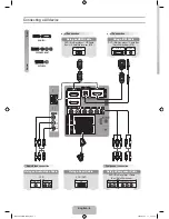
Page 22: ...22 8 7 10 9 6 5 4 3 2 1 A B C D E F G H LC 10A3U SUPPLEMENT OVERALL WIRING DIAGRAM ...

Page 23: ...23 17 16 19 18 15 14 13 12 11 10 LC 10A3U SUPPLEMENT ...

Page 24: ...acitors are µF unless otherwise noted P pF µµF 2 All capacitors are 50V unless otherwise noted 3 All capacitors are Ceramic type unless otherwise noted ML Mylar TA Tantalum PF Polypro Film ST Styrol CAUTION This circuit diagram is original one therefore there may be a slight difference from yours SAFETY NOTES 1 DISCONNECT THE AC PLUG FROM THE AC OUTLET BEFORE REPLACEING PARTS 2 SEMICONDUCTOR HEAT ...

Page 25: ...25 6 5 4 3 2 1 A B C D E F G H LC 10A3U SUPPLEMENT SCHEMATIC DIAGRAM ËSWITCH and R C LED Unit ...

Page 26: ...26 8 7 10 9 6 5 4 3 2 1 A B C D E F G H LC 10A3U SUPPLEMENT Ë MAIN Unit 1 2 ...

Page 27: ...27 17 16 19 18 15 14 13 12 11 10 LC 10A3U SUPPLEMENT ...

Page 28: ...28 8 7 10 9 6 5 4 3 2 1 A B C D E F G H LC 10A3U SUPPLEMENT Ë MAIN Unit 2 2 ...

Page 29: ...29 17 16 19 18 15 14 13 12 11 10 LC 10A3U SUPPLEMENT ...

Page 30: ...30 8 7 10 9 6 5 4 3 2 1 A B C D E F G H LC 10A3U SUPPLEMENT Ë TUNER Unit ...

Page 31: ...31 17 16 19 18 15 14 13 12 11 10 LC 10A3U SUPPLEMENT ...

Page 32: ...32 6 5 4 3 2 1 A B C D E F G H LC 10A3U SUPPLEMENT PRINTED WIRING BOARD ASSEMBLIES Main Unit Side A ...

Page 33: ... FB1203 R1208 R1209 R1210 R1211 C1213 R1235 R1214 R1218 R1222 R1148 C1127 C1223 R1149 C752 SC1203 C1224 R1231 D1201 R1245 R1228 R1244 R1243 C1221 D1203 C1206 C1218 C1212 L1204 L752 C836 C821 R806 IC810 D802 C801 P755 P2002 C751 L804 C809 C848 P2001 R2066 R2067 R2060 R2046 Q2006 R311 R310 C708 Q306 C735 R2041 IC2001 C403 R434 R2042 R435 C404 C741 R2035 R436 C1216 C405 C320 C326 C957 C330 C327 R955 ...

Page 34: ...34 6 5 4 3 2 1 A B C D E F G H LC 10A3U SUPPLEMENT Main Unit Side B ...

Page 35: ...925 R319 R910 R909 C909 C939 C323 R924 C955 C910 C956 C932 R320 R918 R908 R330 C325 C907 R322 IC902 R321 Q305 R966 R968 R323 Q2007 R2082 R2051 R1237 R2052 C201 R209 R2045 R2028 R204 R203 R2031 R201 TP2009 Q204 Q201 C406 R2048 R2044 TP2002 TP2008 R2049 R2043 R210 TP2001 C206 R220 R208 IC201 R2050 R207 R202 IC2002 R2004 R2003 R206 D201 Q2003 IC402 C205 R205 C2009 C410 Q2005 IC704 D2001 R2062 TP2007 ...

Page 36: ...36 6 5 4 3 2 1 A B C D E F G H LC 10A3U SUPPLEMENT TUNER Unit Side A ...

Page 37: ...03 R3413 R3309 R3307 R3405 D3401 R3414 Q3402 Q3401 C3302 C3301 C3405 C3409 C3305 C3304 R3417 R3415 R3303 C3404 R3411 R3412 C3406 R3416 Q3303 Q3304 R3310 C3310 C3309 R3308 R3304 C3407 C3201 L3401 R3334 C3313 R3328 C3308 C3202 Q3302 R3326 R3327 C3204 R3329 C3203 C3210 R3703 SC3401 R3202 R3203 Q3201 Q3202 Q3203 R3201 R3324 R3209 C3209 R3323 C3303 C3208 Q3205 Q3301 R3207 C3306 Q3204 R3208 R3206 R3205 ...

Page 38: ...38 6 5 4 3 2 1 A B C D E F G H LC 10A3U SUPPLEMENT R C LED Unit Side A R C LED Unit Side B SWITCH Unit Side A SWITCH Unit Side B ...

Page 39: ...IECES DE RECHANGE Pour que votre commande soit rapidement et correctement remplie veuillez fournir les renseignements suivants 1 NUMERO DU MODELE 2 NO DE REF 3 NO DE PIECE 4 DESCRIPTION in CANADA Contact SHARP Electronics of Canada Limited Phone 416 890 2100 MARQUE SECTION LIVRAISON DES PIECES DE RECHANGE DUNTKA142DE01 TUNER UNIT PRINTED WIRING BOARD ASSEMBLIES NOT REPLACEMENT ITEM DUNTKA142DE01 T...

Page 40: ... 16W Metal Oxide AA R3319 VRS TQ2BD750JY J 75 1 8W Metal Oxide AA R3320 VRS CY1JF104JY J 100k 1 16W Metal Oxide AA R3321 VRS CY1JF822JY J 8 2k 1 16W Metal Oxide AA R3323 VRS CY1JF101JY J 100 1 16W Metal Oxide AA R3324 VRS CY1JF102JY J 1k 1 16W Metal Oxide AA R3330 VRS TX2HF331JY J 330 1 2W Metal Oxide AB R3331 VRS TX2HF331JY J 330 1 2W Metal Oxide AB R3332 VRS CR3AD3R9JY J 3 9 1W Metal Oxide AC R3...

Page 41: ... S4011 QSW K0088GEZZY J Channel Down AD S4012 QSW K0088GEZZY J MUTE AD S4013 QSW K0088GEZZY J BRIGHT AD S4014 QSW K0088GEZZY J Volume Up AD S4015 QSW K0088GEZZY J Volume Down AD S4016 QSW K0088GEZZY J TV VIDEO AD S4017 QSW K0088GEZZY J DISPLAY AD S4701 QSW S0213CEZZ J MAIN POWER AE MISCELLANEOUS PARTS P4004 QPLGN0564TAZZY J Plug 5 pin AC DUNTKA144DE01 R C LED UNIT TRANSISTORS Q4106 VSDTC144EE 1Y J...

Page 42: ...10 VHDDAN222 1Y J Diode AA D712 VHDDAN222 1Y J Diode AA D753 VHDiMN10 1Y J Diode AB D754 VHDiMN10 1Y J Diode AB D1101 VHD1SS250 1EY J Diode AB D1102 VHDDAN222 1Y J Diode AA D1201 VHDDAN222 1Y J Diode AA D1203 VHDDAN222 1Y J Diode AA PACKAGED CIRCUIT X801 RCRSC0012CEZZY J Crystal AH X901 RCRSB0250GEZZ J Crystal AG X2002 RFiLA0110CEZZ J Filter AD COILS L701 RCiLPA026WJZZ J Coil AD L705 RCiLC0057CEZZ...

Page 43: ...J 100 4V Electrolytic AC C878 RC KZ1025CEZZY J 1 10V Ceramic AB C879 VCKYTV1CF684ZY J 0 68 16V Ceramic AB C902 VCKYCY1EF104ZY J 0 1 25V Ceramic AA C905 VCEAPF1CW106MY J 10 16V Electrolytic AB C906 VCEAPF1CW106MY J 10 16V Electrolytic AB C909 VCKYCY1HB682KY J 6800p 50V Ceramic AA C910 VCKYCY1HB682KY J 6800p 50V Ceramic AA C911 VCEAPF1CW106MY J 10 16V Electrolytic AB C912 VCEAPF1CW106MY J 10 16V Ele...

Page 44: ...e AA R409 VRS CY1JF101JY J 100 1 16W Metal Oxide AA R410 VRS CY1JF101JY J 100 1 16W Metal Oxide AA R411 VRS CY1JF101JY J 100 1 16W Metal Oxide AA R420 VRS CY1JF101JY J 100 1 16W Metal Oxide AA R424 VRS CY1JF101JY J 100 1 16W Metal Oxide AA R430 VRS CA1JF101JY J 100 1 16W Metal Oxide AA R434 VRS CY1JF105JY J 1M 1 16W Metal Oxide AA R435 VRS CY1JF105JY J 1M 1 16W Metal Oxide AA R436 VRS CY1JF105JY J...

Page 45: ...l Oxide AA R1210 VRS CY1JF220JY J 22 1 16W Metal Oxide AA R1211 VRS CY1JF221JY J 220 1 16W Metal Oxide AA R1214 VRS CB1JF101JY J 100 1 16W Metal Oxide AA R1217 VRS CY1JF101JY J 100 1 16W Metal Oxide AA R1218 VRS CA1JF101JY J 100 1 16W Metal Oxide AA R1220 VRS CY1JF472JY J 4 7k 1 16W Metal Oxide AA R1221 VRS CB1JF332JY J 3 3k 1 16W Metal Oxide AC R1222 VRS CB1JF101JY J 100 1 16W Metal Oxide AA R122...

Page 46: ...E 2 4 JBTN 2051CEKA J Operation Button AH 2 5 JKNBP1166CEKA J Power Button AE 2 6 LANGF9600CEFW J Reinforcement Angle AG 2 7 LX NZ3047GEZZ J Antenna Nut x1 AA 2 8 PMLT 0316CEZZ J Spacer x1 AB 2 9 PMLT 0318CEZZ J Button Spacer x2 AB 2 10 PMLT 0356CEZZ J Spacer x1 AB 2 11 PSPAG2004CEZZ J Spacer x1 AB 2 12 PSPAH1001CEZZ J Spacer x1 AD 2 13 PZETZ0015CEZZ J Insulating Sheet AG 2 14 QCNW 5760CEZZ J Conn...

Page 47: ...13 1 1 1 1 16 1 17 1 7 1 6 1 2 1 3 1 16 1 5 R C LED Unit 3 9 14 6 20 11 1 9 1 14 20 3 8 8 3 3 9 1 11 1 7 1 8 1 6 19 15 1 10 SWITCH Unit MAIN Unit TUNER Unit 3 4 3 7 3 5 20 20 2 A 2 14 2 17 3 2 3 1 3 10 3 18 17 3 6 13 16 10 12 2 15 2 13 2 5 2 9 2 8 2 1 2 2 2 4 2 6 2 16 4 5 7 21 2 7 2 3 A 2 12 2 10 2 11 ...

Page 48: ...Z QCNW 5730CEZZ J Antenna Cable AP RRMCG1559CESA J Wireless Remote Control AV TCAUH0011CEZZ J Caution Card AC TiNS 7386CEN1 J Operation Manual AP å UADP 0227CEPZ J AC Adapter BF SPAKC5586CEZZ Packing Case LC 10A3U S A SPAKC5587CEZZ Packing Case LC 10A3U B A SPAKF4002CEZZ Packing Material SPAKP1000CEZZ Wrapping Paper SPAKX2056CEZZ Buffer Material SPAKX2060CEZZ Buffer Material SSAKA0160CEZZ Polyethy...

Page 49: ...ss Remote Control RRMCG1559CESA AC Cord QACCD3099CEZZ Wall Mount Parts LANGU9053CE01 Wrapping Paper SPAKP1000CEZZ Packing Material SPAKF4002CEZZ Packing Case SPAKC5586CEZZ LC 10A3U S SPAKC5587CEZZ LC 10A3U B Carton Label TLABK0001TAZZ Buffer Material SPAKX2060CEZZ Not Replacement Item Buffer Material SPAKX2056CEZZ Polyetlylene Bag SSAKA0160CEZZ A A ...

Page 50: ...r transmitted in any form or by any means electronic mechanical photocopying recording or otherwise without prior written permission of the publisher SHARP CORPORATION AV Systems Group Quality Reliability Control Center Yaita Tochigi 329 2193 Japan TQ1455 S Jan 2003 Printed in Japan MI KG Design and Production Information Design Japan Production Japan ...

Reviews: