Sharp IV-S20, User Manual
The Sharp IV-S20 is an innovative and reliable device equipped with advanced features. Our user manual provides comprehensive instructions for maximizing its potential. Download the manual for free on our website, ensuring a seamless and hassle-free experience with your Sharp IV-S20.
Share
Download


Reviews:
No comments
Related manuals for IV-S20

FSC880
Brand: FALEEMI Pages: 12

SG-100
Brand: Falconeyes Pages: 2

Pinnacle
Brand: FalconEye Electronics Pages: 5

EXA IIa
Brand: Ihagee Pages: 1

IMS-5
Brand: iGUIDE Pages: 41

ISTAR
Brand: NcTech Pages: 9
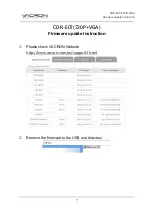
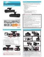
CDR-E07
Brand: Vacron Pages: 5
CDR-E07
Brand: Vacron Pages: 2

TTL
Brand: Zenith Pages: 27

CEC-WP-NV49AB
Brand: Ganz Pages: 8

TR-D2S1
Brand: TRASSIR Pages: 2
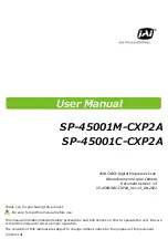
SP-45001C-CXP2A
Brand: JAI Pages: 78

Vivicam 5188
Brand: Vivitar Pages: 2

ViviCam XX14
Brand: Vivitar Pages: 70

M. Zuiko Digital
Brand: Olympus Pages: 58

QNP-6320R
Brand: Hanwha Vision Pages: 15

79068-Auto10
Brand: Arec Pages: 68

TruVision Multi-Imager
Brand: Interlogix Pages: 22


