background image

06/1/5

CD-G15000_FR.fm

TINSZA128AWZZ

MINI COMPONENT SYSTEM

MODEL

CD-G15000

SPEAKER SYSTEM

MODEL

CP-G15000

OPERATION MANUAL

Thank you for purchasing this SHARP product.
To obtain the best performance from this product, please
read this manual carefully. It will guide you in operating your
SHARP product.

CD-G15000

CD-G15000 Mini Component System consisting of CD-G15000
(main unit) and CP-G15000 (front speaker system).

CP-G15000

CP-G15000 Speaker System consisting of GBOXSA133AWM1

(rear speaker system) and CP-SW15000 (active subwoofer).
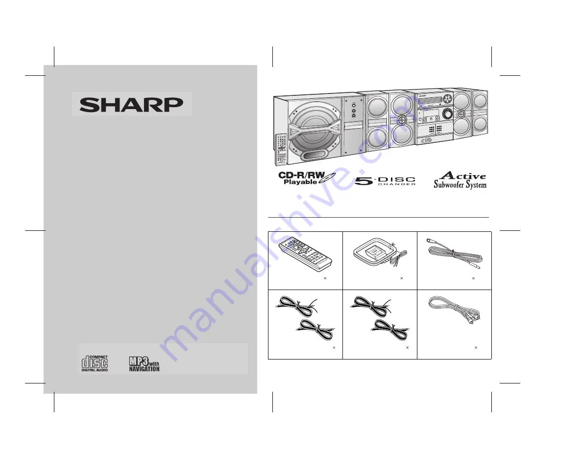
Accessories

Please confirm that the following accessories are included.


Note:


Only the above accessories are included.


Remote control   1 

(RRMCGA090AWSA)

AM loop antenna   1

(QANTL0010AWZZ)

FM antenna   1

(92LFANT1535A)

Wire for front speaker   2

(QCNWHA003AWZZ)

Wire for rear speaker   2

(QCNWHA004AWZZ)

Subwoofer cable   1

(QCNWGA003AWPZ)

Red

Black

Grey

Black

Summary of Contents for CD-G15000

Page 1: ...onent System consisting of CD G15000 main unit and CP G15000 front speaker system CP G15000 CP G15000 Speaker System consisting of GBOXSA133AWM1 rear speaker system and CP SW15000 active subwoofer Accessories Please confirm that the following accessories are included Note Only the above accessories are included Remote control 1 RRMCGA090AWSA AM loop antenna 1 QANTL0010AWZZ FM antenna 1 92LFANT1535...

Page 2: ...g and in particular specifies that the cable ground shall be connected to the grounding system of the building as close to the point of cable entry as practical NOTE This has been tested to the limits for a Class B digital pursuant to Part the These terference in a residential installation This equipment generates uses accordance with the instructions may cause harmful interference to ra dio Howev...

Page 3: ...be blocked by placing the product on a bed sofa rug or other similar surface This product should not be placed in a built in installation such as a bookcase or rack unless proper ventilation is provided or the manufacturer s instructions have been adhered to 11 Power Sources This product should be operated only from the type of power source indicated on the marking label If you are not sure of the...

Page 4: ...s opening or removing covers may expose you to dangerous voltage or other hazards Refer all servicing to qualified service personnel 21 Damage Requiring Service Unplug this product from the wall outlet and refer servicing to qualified service personnel under the following conditions a When the power supply cord or plug is damaged b If liquid has been spilled or objects have fallen into the product...

Page 5: ...ntents Page General Information Precautions 6 Controls and indicators 7 10 Preparation for Use System connections 11 15 Remote control 16 Subwoofer control 17 Basic Operation General control 18 Setting the clock Remote Control only 19 CD or MP3 WMA disc Playback Listening to a CD or MP3 WMA disc 20 23 Advanced CD or MP3 WMA disc playback 24 25 Advanced CD playback 26 MP3 WMA navigation only for MP...

Page 6: ...nit with a voltage other than that which is specified Volume control The sound level at a given volume setting depends on speaker efficiency location and various other factors It is advisable to avoid exposure to high volume levels which occurs while turning the unit on with the volume control setting up high or while continually listening at high volumes Do not place active subwoofer system on th...

Page 7: ... 8 Tape 1 Cassette Compartment 33 9 Headphone Jack 42 10 Game Video Input Jacks 41 11 Disc Tray Open Close Button 21 12 Disc Number Select Buttons 21 13 Volume Control 18 14 CD or Tape Stop Button 22 15 CD Play or Repeat Tape Play Button 21 25 16 CD Track Up or Fast Forward Tape 2 Fast Forward Tuner Preset Up Time Up Button 19 22 32 34 17 CD Track Down or Fast Reverse Tape 2 Rewind Tuner Preset Do...

Page 8: ...Indicator 38 12 FM Stereo Mode Indicator 31 13 FM Stereo Receiving Indicator 31 14 Tape Forward Play Indicator 33 15 Memory Indicator 26 30 32 16 Extra Bass Indicator 18 17 Disc Repeat Play Indicator 25 18 Disc Pause Indicator 22 19 Disc Play Indicator 21 Rear panel Reference page 1 Cooling Fan 15 2 Subwoofer Pre output Jack 14 3 AC Power Cord 14 4 FM 75 Ohms Antenna Jack 12 5 FM Antenna Ground Te...

Page 9: ... Bass Reflex Duct 4 Speaker Terminals Rear speaker 1 Full range Speakers 2 Speaker Terminals Active subwoofer Reference page 1 Subwoofer 2 Bass Reflex Duct 3 Power Switch 17 4 Volume Control 17 5 Crossover Frequency Control 17 6 Cooling Fan 15 7 Subwoofer Input jack 14 8 AC Power Cord 14 1 3 4 2 1 2 1 3 2 4 5 6 7 8 ...

Page 10: ... 10 CD Button 21 11 Tuner Band Button 31 12 Tape 1 2 Button 33 13 Game Video Button 41 14 Disc Track Up or Fast Forward Tape 2 Fast Forward Tuner Preset Up Time Up Cursor Right Button 19 22 27 32 33 37 15 Tuning Down Cursor Down Button 27 16 Volume Up and Down Buttons 18 17 Clear Dimmer Button 18 26 18 Disc Random Button 25 19 Disc Stop Button 22 20 Tape Stop Button 34 21 Memory Button 19 26 32 37...

Page 11: ...S MIN LEFT REAR SPEAKERS FM antenna AM loop antenna Surround speaker left Front speaker left Subwoofer connection see page 15 Speaker connection see page 12 Antenna connection see page 12 To AC outlet To AC outlet Make sure to unplug the AC power cord before making any connections Front speaker right Surround speaker right Active Subwoofer AC power connection see page 14 ...

Page 12: ...antenna for optimum reception Place the AM loop antenna on a shelf etc or attach it to a stand or a wall with screws not supplied Assembling Attaching to the wall Wall Screws not supplied ANTENNA FM 75 OHMS AM GND AM loop antenna FM antenna Connect the speaker wires to the speakers first then to the unit Never mistake the FRONT SPEAKERS and the REAR SPEAKERS terminals Otherwise the unit or the spe...

Page 13: ...hielded Therefore front speakers and active subwoofer do not affect the display even if you use them near the TV However some color variation may occur depending on the type of TV used but rear speakers cannot put near display If color variation occurs Turn off the TV from the power switch After 15 30 minutes turn the TV on again If the color variation is still present Move the speakers further aw...

Page 14: ...cord of the main unit before making any connections 75 OHMS FM GND AM ANTENNA VIDEO OUT RIGHT RATED SPEAKER IMPEDANCE 16 OHMS MIN LEFT REAR SPEAKERS Main unit Subwoofer cable Active subwoofer To subwoofer output jack To subwoofer input jack The unit will start the tape initialization when plugged in to the AC outlet During this process an initializing sound will be heard and the unit cannot be tur...

Page 15: ...he unit will enter the demonstration mode You will see words scroll To cancel the demonstration mode When the unit is in the power stand by mode demonstration mode press the X BASS DEMO button The unit will enter the low power consumption mode 75 OHMS FM GND AM ANTENNA VIDEO OUT RIGHT RATED SPEAKER IMPEDANCE 16 OHMS MIN LEFT REAR SPEAKERS Active subwoofer Main unit To return to the demonstration m...

Page 16: ...ly clean the transmitter on the remote control and the sensor on the unit with a soft cloth Exposing the sensor on the unit to strong light may interfere with operation Change the lighting or the direction of the unit Keep the remote control away from moisture heat shock and vibrations Test of the remote control Check the remote control after checking all the connections see pages 11 15 Point the ...

Page 17: ...ch The speaker unit surface will light up and blink according to BASS SOUND LEVEL During STANDBY MODE DEMO MODE When subwoofer is turned ON the subwoofer unit will emit blinking light During STANDBY MODE ECHO MODE When subwoofer is turned ON no light will be will emitted from the subwoofer unit Notes Observe the following to avoid malfunction and sound distortion Do not set the volume too high on ...

Page 18: ...ired sound mode appears Note The extra bass mode is canceled when the EQUALIZER button is pressed After use Press the ON STAND BY button to enter the power stand by mode Main unit operation When the VOLUME control is turned clockwise the volume will increase When it is turned counterclockwise the volume will decrease Remote control operation Press the VOLUME or button to increase or decrease the v...

Page 19: ... the 12 hour or 24 hour display will be skipped To change the 12 hour or 24 hour display 1 Press the ON STAND BY button to turn the power on 2 Press the CLOCK TIMER button 3 Within 10 seconds press the or button to select CLOCK and press the MEMORY button 4 Press the or button to select 12 hour or 24 hour display and then press the MEMORY button AM 12 00 The 12 hour display will appear AM 12 00 PM...

Page 20: ... time counter in the display may differ from its actual playback time WMA WMA files are Advanced System Format files that include audio files which are compressed with Windows Media Audio codec WMA is developed by Microsoft as an audio format file for Win dows Media Player MP3 or WMA indicator will light up after the unit reads infor mation on an MP3 or WMA disc Auto power on function When you pre...

Page 21: ...o place 3 8 cm disc in the middle of the disc trays 5 Press the button to close the disc tray 1 Due to the structure of the disc information it takes longer to read an MP3 WMA disc than a normal CD approximately 20 to 90 seconds 6 You can place discs on the trays 2 5 by following steps 3 5 7 Press the button to start playback 5 12 cm 3 8 cm CD Total number of tracks on the disc Total playing time ...

Page 22: ...se malfunctions Do not push the disc tray while it is moving If the power fails while the tray is open wait until the power is re stored If the disc tray is stopped with force ER CD20 will appear on the display for 3 seconds and the unit will not function If this occurs press the ON STAND BY button to enter the power stand by mode and then turn the power on again If TV or radio interference occurs...

Page 23: ...rd the next track will be played Playback of the track will begin when its be ginning is reached during fast reverse To change the display MP3 WMA discs only Track up track down is possible only within individual discs Fast forward fast reverse is possible only within individual discs When the end of the last track is reached during fast forward END will appear on the display and CD operation will...

Page 24: ...direct search buttons are pressed while the disc is stopped press the button to start the desired track on the current disc Notes A track number higher than the number of tracks on the disc cannot be selected During random play direct search is not possible 1 Press one of the 1 5 buttons to select the desired disc Selected disc number Within 5 seconds press the button on the main unit Use the dire...

Page 25: ...operation On the other hand the button does not allow you to move to the previous track The be ginning of the track being played will be located In random play the unit will select and play tracks automatically You cannot select the order of the tracks Caution After performing repeat or random play be sure to press the CD button Otherwise the disc s will play continuously To repeat one disc Press ...

Page 26: ...s the ON STAND BY button to enter the stand by mode or change the function from CD to another the programmed selections will not be cleared During the program operation random play is not possible 1 While in the stop mode press the MEMORY button to enter the pro gramming save mode 2 Press one of the 1 5 buttons to select the desired disc Selected disc number 3 Press the direct search buttons on th...

Page 27: ... you enter file names on your PC connect words with hyphens This product recognizes the first word as title 1 second one as title 2 and third one as title 3 Up to three words can be recognized Notes MP3 files must have the extension mp3 WMA files must have the extension wma Up to 100 folders or 300 files can be read on the unit If either limit is exceeded no more folders files are displayed This u...

Page 28: ...MP3 disc 3 Press the CD button to stop playback NAVI READ appears and the display shows the total number of folders and files on the selected disc 4 Press the NAVIGATION button 5 Press the or cursor but ton on the remote control to select FOL T 1 T 2 or T 3 To search files by folder name select FOL will flash The following steps describe file search by folder 6 Press the ENTER button The total num...

Page 29: ...to go to the next page of character display 6 Press the CHARACTER button and the active character will be entered in the 2nd row of the display To delete an entered character move the cursor to the charac ter with the or button and press the CLEAR DIMMER but ton on the remote control 7 Repeat steps 5 and 6 to enter characters In the folder or title name search you do not have to enter the full nam...

Page 30: ...ter the stand by mode with the ON STAND BY button If you press the RANDOM button in the stop mode the MP3 WMA navigation mode will be canceled If tracks are programmed using track numbers see Pro grammed play on page 26 In the MP3 WMA navigation mode only program by folder or title name are played When you exit the mode the program by folder or title name are cleared When you exit the MP3 WMA navi...

Page 31: ...stereo transmission Press the TUNER BAND button to display the ST indicator will appear when an FM broadcast is in stereo If the FM reception is weak press the TUNER BAND button to extinguish the ST indicator The reception changes to monaural and the sound becomes clearer 1 Press the ON STAND BY button to turn the power on 2 Press the TUNER BAND button repeatedly to select the desired frequency ba...

Page 32: ...tore the stations in memory in order starting with preset channel 1 4 Within 30 seconds press the MEMORY button to store that station in memory If the MEMORY and preset number indicators go out before the station is memorized repeat the operation from step 2 5 Repeat steps 1 4 to set other stations or to change a preset station When a new station is stored in memory the station previously memorize...

Page 33: ...p mode of tape operation the main unit enters the stand by mode after 15 minutes of inactivity Before playback For playback use normal or low noise tapes for the best sound Metal or CrO tapes are not recommended Do not use C 120 tapes or poor quality tapes as they may cause malfunctions Before loading a tape into the cassette compartment tighten the slack with a pen or a pencil 1 Press the ON STAN...

Page 34: ...yback or stop mode Before recording When recording important selections make a preliminary test to ensure that the desired material is properly recorded SHARP is not liable for damage or loss of your recording arising from malfunction of this unit The volume and sound controls can be adjusted with no effect on the recorded signal Variable Sound Monitor For recording use only normal tapes Do not us...

Page 35: ...artment with the side to be recorded on facing you Wind past the leader of the tape on which recording cannot be performed 4 Press the button Recording will be paused 5 Press one of the 1 5 buttons to select the desired disc 6 Within 5 seconds press the button to start recording Recording is started from the selected CD When the playback of the last track is finished or the end of the tape is reac...

Page 36: ...button until TAPE 2 appears on the display 3 Press the button 4 Press the button to start erasing Note Make sure that the TAPE 1 is not in use 1 Program discs and tracks See page 26 2 Press the button 3 Press the button 1 Tune in to the desired station See page 31 2 Load a cassette into the TAPE 2 cassette compartment with the side to be recorded on facing you Wind past the leader of the tape on w...

Page 37: ...imer Once timer play and once timer recording works for one time only at a preset time For example if you are away but want to record a program on a radio station Daily timer Daily timer play and daily timer recording works at the same preset time everyday For example set the timer as a wake up call every morning 1 Set the daily timer pages 37 39 2 Set the once timer pages 37 39 Start Daily timer ...

Page 38: ...then press the MEMORY button 8 Set the time to finish as in steps 6 and 7 above White Red 9 Switch input with the or button and then press the MEMORY button To select the timer playback source CD TUNER TAPE 1 or TAPE 2 To select the timer recording source TUNER When you select the tuner select a station by pressing the or button and then press the MEMORY button If a station has not been programmed...

Page 39: ...he GAME INPUT jacks select GAME in step 9 This unit will turn on or enter the power stand by mode automatically however the connected unit will not turn on or off 1 Press the CLOCK TIMER button 2 Within 10 seconds press the or button to select ONCE or DAILY and press the MEMORY button 3 Within 10 seconds press the or button to select ONCE CALL or DAILY CALL and press the MEMORY button The unit ret...

Page 40: ...e CLOCK TIMER button 3 Within 10 seconds press the or button to select SLEEP and press the MEMORY button 4 Press the or button to select the time Maximum 3 hours Minimum 1 minute 3 hours 5 minutes 5 minute intervals 5 minutes 1 minute 1 minute intervals 5 Press the MEMORY button SLEEP will appear 6 The unit will enter the power stand by mode automatically after the preset time has elapsed The volu...

Page 41: ... of Game VCR etc 75 OHMS FM GND AM ANTENNA VIDEO OUT RIGHT RATED SPEAKER IMPEDANCE 16 OHMS MIN LEFT REAR SPEAKERS Game system VCR DVD player etc Red White Yellow Yellow To the line output jacks To video input jack RCA cord not supplied Video cable not supplied Video cable not supplied Yellow TV Yellow Red White 1 Connect a video game system VCR DVD etc to the front GAME INPUT VIDEO AUDIO L and R j...

Page 42: ...ARP dealer or service center General CD player Symptom Possible cause The clock is not set to the correct time Did a power failure occur Reset the clock Refer to page 19 When a button is pressed the unit does not respond Set the unit to the power stand by mode and then turn it back on If the unit still malfunctions reset it Refer to page 44 No sound is heard Is the volume level set to 0 Are the he...

Page 43: ...r sound quality Is it a normal tape You cannot record on a metal or CrO tape Cannot erase completely Sound skipping Is there slack in the tape Is the tape stretched Cannot hear treble Are the capstans pinch rollers or heads dirty Sound fluctuation Cannot remove the tape If a power failure occurs during playback the heads remain engaged with the tape Do not open the compartment with great force Sym...

Page 44: ...L appears Caution This operation will erase all data stored in memory including clock timer settings tuner preset and CD program Before transporting the unit Remove all CDs from the unit Make sure there is no CD in the disc tray Then set the unit to the power stand by mode Carrying the unit with discs left inside can damage the unit Care of compact discs Compact discs are fairly resistant to damag...

Page 45: ...ing a commercial tape head demagnetizer Read the demagnetizer s instructions carefully before use Cleaning the CD pickup lens In order to ensure proper operation of the CD player preventative maintenance cleaning of the laser pickup lens should be performed periodically Lens cleaners are commercially available Contact your local CD software dealer for options Cleaning the cabinet Periodically wipe...

Page 46: ...2 7 8 322 mm Weight P lbs P kg Type 5 disc multi play compact disc player Signal readout Non contact 3 beam semiconductor laser pickup D A converter 1 bit D A converter Frequency response 20 20 000 Hz Dynamic range 90 dB 1 kHz Output power Front speakers 150 watts minimum RMS per channel into 8 ohms from 100 Hz to 20 kHz 10 total harmonic distortion Rear speakers 75 watts minimum RMS per channel i...

Page 47: ...nsions Width 7 11 16 195 mm Height 15 3 4 400 mm Depth 9 5 8 244 mm Weight 4 9 kg 10 8 lbs each Type Full range speaker system 4 10 cm speaker x 2 Maximum input power 150 W Rated input power 75 W Impedance 16 ohms Dimensions Width 5 11 16 145 mm Height 15 3 4 400 mm Depth 9 1 8 231 mm Weight 2 9 kg 6 4 lbs each Power source AC 120 V 60 Hz Power consumption 120 W Output power 400 watts minimum RMS ...

Page 48: ...he sole and exclusive warranties granted by Sharp and shall be the sole and exclusive remedy available to the purchaser Correction of defects in the manner and for the period of time described herein shall constitute complete fulfillment of all liabilities and responsibilities of Sharp to the purchaser with respect to the Product and shall constitute full satisfaction of all claims whether based o...

Reviews: