background image

OPERATION MANUAL
MODE D’EMPLOI
MANUAL DE MANEJO

SHARP CORPORATION

MODEL
MODÈLE
MODELO

CD-BK3100W

MINI COMPONENT SYSTEM
MINI-CHAÎNE
SISTEMA MINI

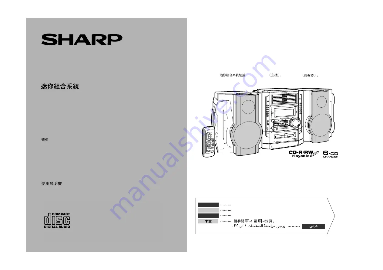
CD-BK3100W Mini Component System consisting of CD-BK3100W (main unit) and CP-
BK3100 (speaker system).

Mini-chaîne CD-BK3100W composée de CD-BK3100W (appareil principal) et de CP-
BK3100 (enceintes acoustiques).

Sistema mini CD-BK3100W que consta de CD-BK3100W (aparato principal) y CP-BK3100
(sistema de altavoces).

CD-BK3100W

CD-BK3100W

CP-BK3100

Please refer to pages E-1 to E-32.

Se reporter aux pages F-1 à F-32.

Consulte las páginas S-1 a S-32.

ENGLISH

FRANÇAIS

ESPAÑOL

Summary of Contents for CD-BK3100W

Page 1: ...0W main unit and CP BK3100 speaker system Mini chaîne CD BK3100W composée de CD BK3100W appareil principal et de CP BK3100 enceintes acoustiques Sistema mini CD BK3100W que consta de CD BK3100W aparato principal y CP BK3100 sistema de altavoces CD BK3100W CD BK3100W CP BK3100 Please refer to pages E 1 to E 32 Se reporter aux pages F 1 à F 32 Consulte las páginas S 1 a S 32 ENGLISH FRANÇAIS ESPAÑOL...

Page 2: ...vases shall be placed on the apparatus CAUTION Laser Diode Properties Material GaAIAs Wavelength 780 nm Emission Duration continuous Laser Output max 0 6 mW z This Mini Component System is classified as a CLASS 1 LASER product z The CLASS 1 LASER PRODUCT label is located on the rear cover z Use of controls adjustments or performance of procedures other than those specified herein may result in haz...

Page 3: ...CDs 14 15 To Specify a Disc to Play 16 Repeat or Random Play 16 Programmed Play 17 Radio Listening to the Radio 18 Listening to the Memorised Station 19 Tape Playback Listening to a Cassette Tape TAPE 1 20 Listening to a Cassette Tape TAPE 2 21 Karaoke Playing Karaoke 22 23 Tape Recording Recording from the Radio 24 Recording from a CD CDs 25 Dubbing from Tape to Tape 26 Advanced Features Timer an...

Page 4: ...t with a higher voltage other than that which is specified is dangerous and may result in a fire or other type of accident causing damage SHARP will not be held responsible for any damage resulting from use of this unit with a voltage other than that which is specified Volume control The sound level at a given volume setting depends on speaker efficiency location and various other factors It is ad...

Page 5: ...rd Tape 2 Fast Wind Tuner Preset Up Button 15 19 21 14 CD Button 14 25 15 Tuner Band Button 18 16 Tape 2 Reverse Play Button with Indicator 21 17 Tape 1 2 Button 20 21 26 18 Video Auxiliary Button 27 29 19 On Stand by Button 10 20 Dimmer Button 10 21 Headphone Socket 29 22 CD or Tape Stop Button with Indicator 15 20 21 23 CD Play or Repeat Tape 1 Play Tape 2 Forward Play Button with Indicator 15 1...

Page 6: ...Tape Reverse Mode Indicator 16 Tape 2 Reverse Play Indicator 17 Tape 1 Play or Tape 2 Forward Play Indicator 18 CD Repeat Play Indicator 19 Karaoke Mode Indicator Rear panel Reference page 1 Transport screw 7 31 2 FM 75 Ohms Aerial Terminal 7 8 3 FM Aerial Earth Terminal 7 8 4 AM Loop Aerial Socket 7 8 5 Span Selector Switch 10 6 Video Auxiliary Audio Signal Input Sockets 29 7 Speaker Terminals 7 ...

Page 7: ...8 12 On Stand by Button 11 13 Extra Bass Button 12 14 CD Random Button 16 15 CD Memory Button 17 16 CD Pause Button 15 17 CD Track Up or Fast Forward Tape 2 Fast Wind Tuner Preset Up Button 15 19 21 18 CD or Tape Stop Button 15 20 21 19 CD Play or Repeat Tape 1 Play Tape 2 Forward Play Button 15 16 20 21 20 Video Auxiliary Button 29 21 Tape 1 2 Button 20 21 26 22 Volume Up and Down Buttons 12 1 2 ...

Page 8: ...E 7 ENGLISH Preparation for Use System Connections System Connections VCR DVD etc AM loop aerial Right speaker Left speaker FM aerial not supplied Transport screw To a wall socket See page 9 ...

Page 9: ... Caution Supplied FM aerial Connect the FM aerial wire to the FM 75 OHMS terminal and position the FM aerial wire in the di rection where the strongest signal can be re ceived Supplied AM loop aerial Connect the AM loop aerial wire to the AM LOOP socket Position the AM loop aerial for optimum reception Place the AM loop aerial on a shelf etc or attach it to a stand or a wall with screws not suppli...

Page 10: ...wdriver until the appropriate voltage num ber appears in the window 110 V 127 V 220 V or 230 V 240 V AC Connecting the AC power lead After making all connections plug the unit If you plug the unit first the unit will enter the demonstration mode see page 10 Note Unplug the AC power lead from the wall socket if the unit will not be in use for a pro longed period of time AC Plug Adaptor In areas or ...

Page 11: ... the X BASS DEMO button The demonstration mode will be cancelled and the display will disappear To return to the demonstration mode When the unit is in the power stand by mode press the X BASS DEMO button again Note When the power is on the X BASS DEMO button can be used to select the extra bass mode To turn the power on Press the ON STAND BY button to turn the power on To set the unit to stand by...

Page 12: ...e batteries UM SUM 3 R6 HP 7 or similar z Periodically clean the transmitter on the remote control and the sensor on the unit with a soft cloth z Exposing the sensor on the unit to strong light may interfere with operation Change the lighting or the direction of the unit z Keep the remote control away from moisture heat shock and vibrations Test of the remote control Face the remote control direct...

Page 13: ...ter the extra bass mode which emphasises the bass frequencies and X BASS will appear To cancel the extra bass mode press the X BASS DEMO X BASS button Equalizer When the EQUALIZER EQUALIZER MODE button is pressed the current mode setting will be displayed To change to a different mode press the EQUALIZER EQUALIZER MODE button repeatedly until the desired sound mode appears X BASS indicator The sou...

Page 14: ...appear AM 0 00 PM 11 59 Note that this can only be set when the unit is first installed or it has been reset Refer to Clearing all the memory reset on page 31 for details 4 Press the TUNING TIME or button to adjust the hour and then press the MEMORY SET button z Press the TUNING TIME or button once to advance the time by 1 hour Hold it down to advance continuously z When the 12 hour display is sel...

Page 15: ...ext page 1 Press the ON STAND BY button to turn the power on 2 Press the CD button 3 Press the 1 button to open the disc tray 1 4 Place the CD on the disc tray 1 label side up Be sure to place 8 cm 3 CD in the middle of the disc trays 5 Press the 1 button to close the disc tray 1 Music schedule Total number of tracks Total playing time Means disc inside The music schedule will display only the num...

Page 16: ...inning of a track on a single disc only To locate the desired portion Notes z Normal playback will resume when the or button is released z You can locate the desired portion on a single disc only z When the end of the last track is reached during fast forward DISC END will appear on the display and CD operation will be paused When the beginning of the first track is reached during fast reverse the...

Page 17: ...ay Press the button Notes z If you press the button during random play you can move to the track selected next by the random operation On the other hand the button does not allow you to move to the previous track The beginning of the track being played will be located z In random play the CD player will select and play tracks automatically You cannot select the order of the tracks Caution After pe...

Page 18: ...ce z Even if you press the ON STAND BY button to enter the stand by mode or change the function from CD to another the programmed selections will not be cleared z During programme operation random play is not possible 1 Whilst in the stop mode press the MEMORY SET MEMORY button to enter the programming save mode 2 Press one of the 1 6 buttons to select the desired disc Selected disc number 3 Press...

Page 19: ...BAND button repeatedly to select the desired frequency band FM or AM 3 Press the TUNING TIME or button to tune in to the desired station Manual tuning Press the TUNING TIME button as many times as required to tune in to the de sired station Auto tuning When the TUNING TIME button is pressed for more than 0 5 seconds scanning will start automatically and the tuner will stop at the first receivable ...

Page 20: ... starting with preset channel 1 4 Within 30 seconds press the MEMORY SET button to store that station in memory If the MEMORY and preset number indicators go out before the station is memorised repeat the operation from step 2 5 Repeat steps 1 4 to set other stations or to change a preset sta tion When a new station is stored in memory the station previously memorised will be erased Press the PRES...

Page 21: ...e not recommended z Do not use C 120 tapes or poor quality tapes as they may cause mal functions z Before loading a tape into the cassette compartment tighten the slack with a pen or a pencil 1 Press the ON STAND BY button to turn the power on 2 Press the TAPE 1 2 button to select TAPE 1 3 Open the cassette door by pushing the area marked PUSH EJECT 4 Load a cassette into the TAPE 1 cassette compa...

Page 22: ...ccurs during tape operation the tape head will remain engaged with the tape and the cassette door will not open Wait until power is restored 1 Press the ON STAND BY button to turn the power on 2 Press the TAPE 1 2 button to select TAPE 2 3 Open the cassette door by pushing the area marked PUSH EJECT 4 Load a cassette into the TAPE 2 cas sette compartment with side A facing you 5 Press the button t...

Page 23: ...one to the MIC socket z Use a microphone with a 6 3 mm 1 4 plug an impedance of 600 ohms z If a microphone whose sensitivity is too high is used howling may be gener ated z Unidirectional microphone is more appropriate for vocal use z Use a standard plug adaptor when using a microphone with a 3 5 mm 1 8 diameter plug 3 Press the ON STAND BY button to turn the power on 4 Press one of the CD TUNER B...

Page 24: ... by mode or when the function is changed from the CD to another function To change general stereo source to karaoke source Even ordinary discs and tapes not recorded specifically for karaoke can be used as karaoke discs and tapes just by toning down the main vocal Press the KARAOKE MODE button until V CANCEL appears in the display z will appear Notes z Use discs which have been recorded in stereo ...

Page 25: ...ilst recording an AM station move the AM loop aerial 1 Tune in to the desired station See page 18 2 Load a cassette into the TAPE 2 cassette compartment with side A facing you Wind past the leader of the tape on which recording cannot be performed 3 Press the button to choose one side or both sides To record on both sides To record on only one side 4 Press the REC PAUSE but ton Recording will be p...

Page 26: ...e CD button and load the desired disc 4 Press the button to choose one side or both sides To record on both sides To record on only one side 5 Press the REC PAUSE but ton Recording will be paused 6 Press one of the 1 6 buttons to start recording z To record on both sides begin on side A If recording is started from side B the tape will not switch over to side A z Recording is started from the sele...

Page 27: ...commended that the recording tape is the same length as the master tape 3 Press the TAPE 1 2 button un til TAPE 1 appears on the dis play The reverse mode will be set to 4 Press the REC PAUSE but ton Recording will be paused 5 Press the button to start recording 1 Load the tape to be erased into the TAPE 2 cassette compartment with the side to be erased facing toward you 2 Press the TAPE 1 2 butto...

Page 28: ...recording Load a cassette for recording in the TAPE 2 cassette compartment 1 Press the ON STAND BY button to turn the power on 2 Press the CD TUNER BAND or TAPE 1 2 button to select the desired function To select the timer playback source CD TUNER BAND or TAPE 1 2 To select the timer recording source TUNER BAND When you selected the TUNER BAND tune in to the desired sta tion 3 Adjust the volume us...

Page 29: ...t TUNER it will enter the stand by mode one hour after the tim er playback starts In timer recording When the recording tape reaches its end the timer recording will end and the unit will enter the stand by mode z Once the time is set the setting will be retained until a new time is entered z When performing timer playback or recording using another unit connected to the VIDEO AUX sockets select V...

Page 30: ...pedance The recommended impedance is 32 ohms z Plugging in the headphones disconnects the speakers automatically Adjust the volume using the VOLUME control VCR DVD etc To the line output sockets Red RCA lead not supplied White Red White 1 Use a connection lead to connect the VCR DVD etc to the VIDEO AUX sockets When using video equipment connect the audio output to this unit and the video output t...

Page 31: ...f a track z Is the unit located near excessive vibra tions z Is the disc very dirty z Has condensation formed inside the unit Symptom Possible cause z Radio makes unusual noise con secutively z Is the unit placed near the TV or comput er z Is the FM aerial or AM loop aerial placed properly Move the AC power lead away from the aerial if located near Symptom Possible cause z Cannot record z Is the e...

Page 32: ...dling parts z Dirty heads capstans or pinch rollers can cause poor sound and tape jams Clean these parts with a cotton swab moistened with commercial head pinch roller cleaner or isopropyl alcohol z When cleaning the heads pinch rollers etc unplug the unit which contains high voltages z After long use the deck s heads and capstans may become magnetised causing poor sound Demagnetise these parts on...

Page 33: ...r and tweeter 80 W 40 W 40 W Subwoofer 120 W 60 W 60 W RMS 184 W 92 W 92 W 0 9 T H D Main speaker woofer and tweeter 74 W 37 W 37 W Subwoofer 110 W 55 W 55 W Output terminals Speakers 6 ohms Headphones 16 50 ohms recommended 32 ohms Input terminals Video Auxiliary audio signal 500 mV 47 kohms Microphone 1 mV 600 ohms Type 6 disc multi play compact disc player Signal readout Non contact 3 beam semi...

Page 34: ... tv dvd and othes Manual users user manuals user guide manual owners manual instruction manual manual owner manual owner s manual guide manual operation operating manual user s manual operating instructions manual operators manual operator manual product documentation manual user maintenance brochure user reference pdf manual Downloaded from http www usersmanualguide com ...

Reviews: