Seiko TH-2B, Instruction Manual
The Seiko TH-2B Instruction Manual is a comprehensive user guide that ensures a smooth and hassle-free experience with your device. Easily download this manual for free from our website, providing you with step-by-step instructions and valuable insights to maximize the functionality of your Seiko TH-2B.
Share
Download


Reviews:
No comments
Related manuals for TH-2B

MF 4640
Brand: Sagem Pages: 104

CLF-4455
Brand: Ultratec Pages: 11

M19 Series
Brand: DeLuxe Stitcher Pages: 48

CK-441
Brand: Chikon Pages: 17

AA-2
Brand: Siruba Pages: 10

LAVINA ELITE L30LEU
Brand: Superabrasive Pages: 40

G0518
Brand: Garden Gear Pages: 16

AMS-221EN/IP-420
Brand: JUKI Pages: 121

NC81200 CLASSES
Brand: Carpet Sergers Pages: 30
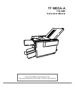
TF MEGA-A
Brand: Hefter Pages: 71

CombBind C20
Brand: GBC Pages: 9
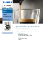
Saeco HD 8327
Brand: Philips Pages: 2

KX-TG2257
Brand: Panasonic Pages: 3

KX-TG2247F
Brand: Panasonic Pages: 2

KX-TG2224W - 2.4 GHz Digital Cordless Phone
Brand: Panasonic Pages: 2

KX-TG2226
Brand: Panasonic Pages: 3

KX-TG1843AL
Brand: Panasonic Pages: 2

kX-TG2323C
Brand: Panasonic Pages: 40


