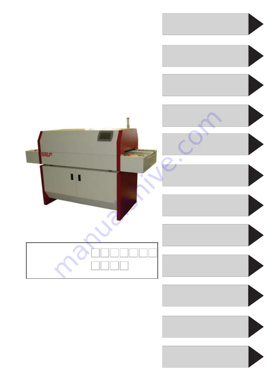
background image

Serial number:

Year of manufac-
turing:

Keep this manual for a later use.

2

1

3

4
5

6

7

8

9

10

11

12

Schematic diagram

Options and  
spare parts

Notes

© SEF Systec GmbH, December 2015
Translation of original instruction.
Subject to technical changes.

Operating Manual

System settings

Operation and  
start-up

Transport and  
installation

Technical data

Safety instructions

Preface

Warranty

Profile administration

Maintenance and  
service

p


551.10  

4

 heating zones

p


551.15  

5

 heating zones

p


551.19  

8

 heating zones

Summary of Contents for 551.10

Page 1: ...F Systec GmbH December 2015 Translation of original instruction Subject to technical changes Operating Manual System settings Operation and start up Transport and installation Technical data Safety instructions Preface Warranty Profile administration Maintenance and service p 551 10 4 heating zones p 551 15 5 heating zones p 551 19 8 heating zones ...

Page 2: ......

Page 3: ...Spare parts 2 7 Safety notes for installation and initial start up 2 9 Connection conditions 2 9 Location 2 9 Exhaustion 2 9 Safety notes for daily start of operation and automatic operation 2 11 Safety at the working place 2 11 Solder paste and chip adhesive 2 11 Protective equipment 2 11 Failures 2 13 Optical signals 2 13 Safety notes for maintenance and service 2 14 Five safety rules 2 14 Dismo...

Page 4: ... Electrical connection values 4 7 Allowed climatic demands 4 7 Allowed component sizes 4 7 Characteristics 4 7 Emissions 4 7 Functional scheme 551 10 4 heating zones 4 8 Funktional scheme 551 15 5 heating zones 4 8 Funktional scheme 551 19 8 heating zones 4 8 Functional scheme 4 9 Heating chamber 4 9 Cooling zone Exhaust hood 4 9 Transport 4 9 Operating panel 7 touch screen 4 11 Controller SBCC Bo...

Page 5: ... Name plate 400VAC N PE 5 10 Power supply 400VAC N PE 5 10 Name plate 220VAC D 5 11 Power supply 220VAC D 5 11 Exhaust connection 5 13 Interfaces 5 14 Main switch 5 14 Operating switch On Off 5 14 Operation by touch panel 5 14 Profile setting 5 14 Integrated temperature profiler 5 14 Final check 5 15 Dismounting storage and preservation 5 16 Dismounting 5 16 Short term out of operation 5 16 Preser...

Page 6: ... 7 13 Create soldering or curing profile 7 13 Adjust nominal temperature 7 13 Adjust conveyor speed 7 15 Save program 7 17 Overwrite program 7 18 Turn the soldering system on off 6 11 Main switch 6 11 Turn soldering system on 6 11 The system screen 6 11 Basic structure of screen 6 12 System display 6 13 Operating modes of soldering systems series 551 6 13 Menu structure Load program 6 14 Load prog...

Page 7: ...ructions for opening and closing the hood 9 3 Set system out of operation 9 3 Opening the hood 9 4 Closing the hood 9 5 Cleaning and maintenance intervals 9 6 Cleaning 9 6 Maintenance 9 6 Save program 7 19 Option pin chain conveyor 7 21 Adjust working width of pin chain conveyor 7 21 Start production 7 22 Start system 7 22 Heat up phase 7 22 Fill the oven 7 24 Start soldering or curing process 7 2...

Page 8: ... triangle circuit 9 26 Mounting plate inlet 9 27 Mounting plate outlet 9 27 Exchange blower 9 29 Dismount blower 9 29 Exchange fan 9 31 Dismount fan 9 31 Exchange heating elements of the upper heating modules 9 33 Dismount heating module 9 33 Exchange upper heating element 9 36 Mount upper heating module 9 37 Exchange heating elements of lower heating zones 9 38 Dismount lower heating element 9 39...

Page 9: ...rver computer directories 11 10 Soldering system software RO R2 settings 11 10 Server software setup 11 12 Port setup 11 13 Set admin interface 11 13 Create user 11 14 Assign directory 11 15 Set up external operation 11 18 Option Communication Package external operation 11 19 Configure VNC 11 19 Option lamp pole for soldering systems 551 10 15 20 11 21 Operating mode of the soldering system series...

Page 10: ...Table of content Table of content 551 19 12 2015 Page 0 10 ...

Page 11: ...umed y By reading this manual you help to avoid dangers reduce repair costs and downtimes as well as raise the depend ability and life time of the system y Observe the safety instructions We will not take any liability for damages or interruptions cause by non observance of this information Use the soldering system only in proper condition according to the intended use safety and danger conscious ...

Page 12: ... be found before important informations or explana tions regarding better handling of the system To be found before general listings y To be found before working or operating steps to be conducted in the described order This symbol indicates information that relate to a product variant Key These figures mark switches or keys Display These figures mark display elements ...

Page 13: ...erator and operating staff 2 7 Legal safety requirements 2 7 Personal safety 2 7 Reference to other suppliers 2 7 Spare parts 2 7 Safety notes for installation and initial start up 2 9 Connection conditions 2 9 Location 2 9 Exhaustion 2 9 Safety notes for daily start of operation and automatic operation 2 11 Safety at the working place 2 11 Solder paste and chip adhesive 2 11 Protective equipment ...

Page 14: ... will find different warning and additional signs Safety signs IT IS FORBIDDEN to remove warning notes safety symbols and designation labels or to interfere their clear recognizability Warning of electrical voltage Warning of high temperatures Warning of entanglement hazard at the inlet and outlet ...

Page 15: ...ions in this manual y Observe the safety instructions y Start your work with caution and safety conscious y Each person working with this system should have read and understood the complete operation manual and espe cially this chapter Not only the general safety instructions in this chapter have to be followed but also the special safety instructions in the other chap ters y Keep this manual alwa...

Page 16: ...ts EN 60519 1 Safety in electroheat installations Part 1 general requirements EN 60519 2 Safety in electroheat installations Part 2 Particular requirements for resistance heat ing equipment EN 61000 6 1 Electromagnetic compatibility EMC Part 6 1 Ge neric standards Immunity for residential commer cial and light industrial environments IEC 61000 6 1 2005 EN 61000 6 2 Electromagnetic compatibility Ge...

Page 17: ...s manual Remaining risks are not obvious risks caused by the system Even if the system is used properly risks for the life or physical condition of the user or third parties respectively impairment of the system or other material assets can not be completely excluded Remaining risks Please observe The intended use includes also the observance of the prescribed installation and operating conditions...

Page 18: ...Safety instruc tions have been read and understood that all safety instructions are trained regularly once a year that the operating staff is informed about kind and cover age of the work as well as about possible dangers by the safety representative or within a training that not qualified persons don t work at the system that service staff is authorised by a user specific training Skilled and qua...

Page 19: ...e system or proceeding maintenance work the staff should be in a good health The staff should not have taken any medication or other agents decreasing the reaction time Each method of operation which is impacting the personal safety must be defaulted Responsibility of operator and operating staff Use only original spare parts Reference to other suppliers Operate the system only with accessories an...

Page 20: ...ty instructions 551 15 12 2015 Working areas Overview of working areas 1 Charging zone 2 Emergency stop switch 3 Operating switch On Off 4 Operating and programming via touch panel 5 Lamp pole 6 Discharging zone 1 3 6 2 4 5 750 800 60 898 ...

Page 21: ... vapours could be harmful to health y Connect the soldering system with your house internal ex haust system or with an air washer system The exhaust system must have an minimum capacity of 270m h y Don t let the vapours escape to the production area y Provide an adequate air ventilation at the place of produc tion y It is absolutely important to observe the safety and processing notes of the solde...

Page 22: ...ety instructions 551 15 12 2015 Working areas Overview of working areas 1 Charging zone 2 Emergency stop switch 3 Operating switch On Off 4 Operating and programming via touch panel 5 Lamp pole 6 Discharging zone 1 3 6 2 4 5 750 800 60 898 ...

Page 23: ...nd chip adhesive The operator must grant cleanness and clearness of the working place by corresponding instructions and controls Safety at the work ing place The operator is responsible that personal protective clothes is worn according to the device safety laws The valid accident prevention provisions give information for which work and work ing places respectively personal protective clothes mus...

Page 24: ...ety instructions 551 15 12 2015 Overview of working areas 1 Charging zone 2 Emergency stop switch 3 Operating switch On Off 4 Operating and programming via touch panel 5 Lamp pole 6 Discharging zone Working areas 1 3 6 2 4 5 750 800 60 898 ...

Page 25: ...ilures emergency stop pressed and internal temperature too high the following messages appear on the touch screen the error message Emergency stop ERR the machine status is changing to COOLING the virtual red lamp shows the status not ready If the option lamp pole is installed the red lamp also shows the sta tus not ready If a failure appears which can cause a risk for persons system or environmen...

Page 26: ...th the operating switch On Off only the internal control voltage 24V will be swit ched off Contactor transformator and WLAN power socket won t be switched off by this way y Before starting any maintenance or service work the sys tem must be switched off and secured against unintended restart with a lock y Remove the mains connector from power supply before processing any service work at the solder...

Page 27: ...the safety devices again and check them for function Dismounting of safety devices Observe the maintenance cycles mentioned in this manual CAUTION Crushing hazard y Don t grasp in the oven while opening or closing the hood y When working with opened hood make sure that the hood rest is snapped and so the hood is protected against unin tended lowering CAUTION Risk of burns due to operating temperat...

Page 28: ...al and provincial law Especially obligatory surveyed substances and material will not always be disposed of by the local authorities In these cases the operator is obligated to dispose of the mate rials by himself in compliance with the relevant legal regulations y Please consult your environmental protection agency for further information on proper disposal of these substanc es Vaporised residues...

Page 29: ...rranty 551_19 12 2015 Table of content Warranty 3 2 Rights of use 3 2 Assignment of the rights of use 3 2 Liability 3 2 Reshipment 3 2 Modifications or improvements of the product 3 3 Special restrictions 3 3 Caveat emptor 3 3 ...

Page 30: ...lid subject to the provisions of our General terms and conditions We will carry out repairs free of charge within a period of 18 months max 6000 operation hours after free return of the product The warranty begins with the day of delivery Within the warranty period we will remedy all product mal functions which are the result of defective workmanship free of charge subject to the condition that th...

Page 31: ...in their original or modified form It is prohibited to modify the deliv ered product or parts of it The general terms and conditions of the APT GmbH Automa tion und Produktionstechnik apply The place of jurisdiction and place of fulfilment is Uelzen Excluded from the warranty are consumables and wearing parts defects or malfunctions resulting from incorrect handling or improper operation Damages w...

Page 32: ...Page 3 4 3 0 Warranty Warranty 551_19 12 2015 ...

Page 33: ...Electrical connection values 4 7 Allowed climatic demands 4 7 Allowed component sizes 4 7 Characteristics 4 7 Emissions 4 7 Functional scheme 551 10 4 heating zones 4 8 Funktional scheme 551 15 5 heating zones 4 8 Funktional scheme 551 19 8 heating zones 4 8 Functional scheme 4 9 Heating chamber 4 9 Cooling zone Exhaust hood 4 9 Transport 4 9 Operating panel 7 touch screen 4 11 Controller SBCC Boa...

Page 34: ...4 0 Technical data Page 4 2 Technical Data 551_15 04 2015 Dimensions of the soldering system 551 10 551 15 All dimensions in millimetre mm Dimensions of the soldering system with opened hood ...

Page 35: ...ture during transport and storage DIN EN 60204 1 4 5 25 up to 55 C Maximum allowed air humidity 50 40 C DIN EN 60204 1 4 4 4 90 20 C no condensation PCB component sizes Minimum size 15 x 10 mm Working width mesh belt 440 mm Useable working width mesh belt 405 mm Working width pin chain optional 35 400 mm Maximum assembly height 45 mm incl fixture Maximum reflow temperature 280 C Conveyor speed 15 ...

Page 36: ... data Page 4 4 Technical Data 551_15 04 2015 Dimensions of the soldering system 551 10 15 with power supply 220V triangle circuit All dimensions in millimeter mm Dimensions of the solde ring system with opened hood ...

Page 37: ...ional module All wires will be ad apted to the higher current and additional fuses will be installed Depth 824 mm Width 2006 mm Height 554 mm Depth opened 1050 mm Depth opened with option light pole 1170 mm Height opened without base cabinet approx 1000 mm Weight without options 175 kg Painting RAL 9010 pure white RAL 3001 signal red Protection class IP 20 Continuous sound pressure level 60dB A El...

Page 38: ...4 0 Technical data Page 4 6 Technical Data 551_15 04 2015 Dimensions of the soldering system 551 19 All dimensions in millimetre mm Dimensions of the soldering system with opened hood ...

Page 39: ...p to 40 C Ambient temperature during transport and storage DIN EN 60204 1 4 5 25 up to 55 C Maximum allowed air humidity 50 40 C DIN EN 60204 1 4 4 4 90 20 C no condensation PCB component sizes Minimum size 15 x 10 mm Working width mesh belt 440 mm Useable working width mesh belt 405 mm Working width pin chain optional 35 400 mm Maximum assembly height 45 mm incl fixture Maximum reflow temperature...

Page 40: ... ovens of the series 551 1X are designed as a desktop unit and modular The heat ing chamber can accommodate five zones which can be designed as either heating or cooling zone Structure of the heating chamber 551 10 4 heating zones 1 cooling zone Structure of the heating chamber 551 15 5 heating zones with external cooling zone Functional scheme 551 19 8 heating zones ...

Page 41: ...u ally The maximum power consumption of soldering ovens 551 10 551 15 is limited by the controller to 11 kW the power consumption of sol dering oven 551 19 at 22 kW to avoid overloading the mains supply during the heating phase The available heating capacity is split as required by an intelligent software control to all heating zones The upper part of the heating chamber contains also a cooling zo...

Page 42: ...4 0 Technical data Page 4 10 Technical Data 551_15 04 2015 ...

Page 43: ... SBCC micro controller form an assembly group Display 7 touch screen Resolution 800 480 pixel Controller SBCC Board Processor TI Sitara AM3354 720 MHz ARM Cortex A8 RAM 256MB DDR3 SDRAM ROM 128MB NAND Flash RTC DS1339 Real Time Clock Internal features SBCC 10 100Mbps Ethernet 2x High Speed USB 2 0 port True colour LCD controller CAN interfaces 4 5 wire touch screen interface Several peripheral int...

Page 44: ... 4 12 Technical Data 551_15 04 2015 24V power supply Battery holder CR2032 Ethernet optional LAN WLAN leaded to outside USB 2 0 leaded to outside CAN Bus communication electronics touch panel 4 5 wire touch screen inter face ...

Page 45: ... mini mize the software work The configuration of the modules will be done manually but wiull be checked when switching on the system All entries like program loading editing saving profile measurement setup etc are done via the touch panel The program data and measurement results can be saved via the touch screen and printed on a USB printer Modules assembly groups touch screen Entry and visualis...

Page 46: ...a 551_15 04 2015 Central electrics with controller RO R2R Central electrics 551 10 551 15 Central electrics 551 19 with two controllers RO R2R Controller RO R2R Master Controller RO R2R Slave Line contactor K1 K2 Input fuses and power supply T0 ...

Page 47: ...tart and or regularly in operation Current measurement at all fans short drive of all fans for error diagnosis Current measurement at all heaters short drive of all heaters for error diagnosis Sensor test Recognition of thermocouples check for break damage In the soldering ovens 551 10 and 551 15 the complete machine elec tronics will be found on the mounting plate below the inlet zone For the eig...

Page 48: ...V power sup ply Terminals 2x Load contactor safe cut off in case of error Controller board RO R2R Pre fuse F1 exhaust box 24V power supply Terminals Load contactor Controller board RO R2R Pre fuse F3 F4 24V power supply power WLAN Version 3 400VAC Y 16A CEECON Version 3 220VAC 60Hz 32A ...

Page 49: ...tors Voltage supply Voltage supply by external power supply 24VDC 5A Communication CAN IN communication with SBCC controller CAN OUT connection of enhancements second central electronics Drive of mesh belts 24V gear motor with encoder speed control conveyor via hall sensor Monitoring mesh belt via light barrier Blower Fan 230V 5x blower for upper zones 1 5 2 per fan per module 1x fan for internal ...

Page 50: ...Temp u Emergency Stop jumpered n c n c Heating zone 5 above Heating zone 5 above Heating zone 5 below Heating zone 6 above Heating zone 6 above Heating zone 6 below Heating zone 7 above Heating zone 7 above Heating zone 7 below Heating zone 8 above Heating zone 8 above Heating zone 8 below reserve reserve reserve 400VAC 16A 50Hz X2 X3 X4 X5 X6 X7 X8 X9 X10 X11 X12 X13 X14 X15 X16 X1 CAN connection...

Page 51: ... fuses of the first four heating zones Slave Controller RO R2R mounting plate inlet The controller RO R2R on the mounting plate below the outlet zone assumes the master function It controls the heating coils and fans of the heating zones 5 8 the transfer and monitors the thermal fuses of the rear heating chambers As Master the controller is also responsi ble for the safety functions and for commun...

Page 52: ...4 0 Technical data Page 4 20 Technical Data 551_15 04 2015 adjustable transfer bar Handwheel 1 ...

Page 53: ...ize only option pin chain conveyor Working width pin chain 35 400 mm Pin length 4 mm maximum assembly height 45 mm incl support maximum reflow temperature approx 280 C Conveyor speed 10 70 cm min The adjustable rear transfer bar can be moved with the handwheel 1 to the required working width The front transfer bar is fixed and can t be moved Allowed component sizes pin chain conveyor Parameters pi...

Page 54: ...4 0 Technical data Page 4 22 Technical Data 551_15 04 2015 ...

Page 55: ...tely supplied stable cabinet for safe placement the sol dering oven The cabinet has behind its two front doors plenty of storage space for your soldering equipment Depth 750 mm Depth opened 1450 mm Width 1400 mm Height 710 mm Weight approx 90 kg Colour RAL 9010 pure white RAL 3001 signal red Base cabinet 551 10 1 Technical data base cabinet ...

Page 56: ...4 0 Technical data Page 4 24 Technical Data 551_15 04 2015 ...

Page 57: ...3 h The emissions in the exhaust air depend on the used solder paste and chip adhesive Electrical connection 230VAC 50 Hz SK1 Option exhaust box 551 10 2 Technical data exhaust box CAUTION Danger of toxication On a continuous base the arising solder or adhesive vapours are harmful to health y The machine must necessarily be connected to an exhaust system or an air washing unit The exhaust system m...

Page 58: ...4 0 Technical data Page 4 26 Technical Data 551_15 04 2015 ...

Page 59: ...Dimensions and data of the soldering system 551 19 5 8 System 551 19 setup and alignment 5 9 Align soldering system horizontally 5 10 Mains supply 5 10 Name plate 400VAC N PE 5 10 Power supply 400VAC N PE 5 10 Name plate 220VAC D 5 11 Power supply 220VAC D 5 11 Exhaust connection 5 13 Interfaces 5 14 Main switch 5 14 Operating switch On Off 5 14 Operation by touch panel 5 14 Profile setting 5 14 I...

Page 60: ...y Please note the instructions on the packaging Transport notes on the packaging Transport notes Point to fix a chain or a rope at the packaging Indication of center of gravity of packaging Caution fragile Don t topple or tilt over Attention do not use hand hooks Protect from direct sunlight This side up Transport only with this side up Arrows point upwards ...

Page 61: ...ed EMC protection measures and the warranty expires Anyone who is dismounting or changing safety installations of the soldering system is acting grossly negligent and against the valid guidelines SEF Systec GmbH won t take any liability for damages to persons or property caused by changed safety installations The mounting of additional installations is only allowed after written approval of the ma...

Page 62: ... panel 9 USB interface 6 Lamp pole 15 Exhaust socket 11 SMEMA inlet 10 internal temperature profiler 17 SMEMA outlet 1 Base cabinet optional 2 Soldering system 551 10 4 IR sensor PCB recognition 16 LAN connection 12 Mains connection exhaust box 14 mains line 8 extern cooling module 551 15 3 Operating switch On Off ...

Page 63: ...very Checking scope of delivery y After unpacking and checking the faultless condition of the system as well as the scope of delivery you can start with the transport on pallet to the installation site For transportation or service please keep the packaging y Check immediately if there are any transport damages If so make a note on the delivery note and contact immedi ately the forwarder as well a...

Page 64: ...pprox 280 C PCB cooling 551 10 cooling module zone 5 2 blowers 551 15 cooling module outlet 3 fans Continuous sound pressure level 60dB A Power supply Connection value 3 400VAC Y optional 3 220VAC 230 400VAC 50Hz 16A CEECON 220VAC 60Hz 32A PNom approx 5000 W Power standby 100 C 2100 W Media supply exhaust air Exhaust socket Connection Ø 60 mm Necessary exhaust air volume 270 m h Dimensions and dat...

Page 65: ... is designed as a desk model The working table must be stable and capable of the soldering sys tems weight We recommend to use the special designed base cabinet 551 10 1 with a lot of stowage for the safe set up of the soldering system NOTICE Risk of breakage The soldering system 551 10 15 has a weight of 175 kg y The working table must be capable of the soldering sys tems weight and the dimension...

Page 66: ...mm DxWxH Weight 450 kg Min PCB size 15 x 10 mm working width mesh belt 405 mm Colour RAL 9010 3001 Max reflow temperature approx 280 C PCB cooling cooling modules zones 9 10 each two blowers Continuous sound pressure level 60dB A Power supply Connection value 3 400VAC Y 230 400VAC 50Hz 32A CEECON PNom approx 10000 W Power standby 100 C 3500 W Media supply exhaust air Exhaust socket Connection Ø 60...

Page 67: ...s a weight of about 450 kg y Ensure that the location of the control system is designed for the weight System 551 19 setup and alignment y Move the soldering system 551 19 on the transport pallet to the final place of production with an appropriate means of transport such as hand lift or fork truck y Remove the four securing screws M10x70 which are screwed from underneath through the transport pal...

Page 68: ...ns supply Power supply 400VAC N PE In standard soldering systems of the series 551 are equipped with a 400V CEECON connector at a 5m power line y Provide the mains connection 400VAC N PE 50 Hz with the 16A 551 10 15 or 32A 551 19 CEECON connector Danger Pay attention to the specifications on the name plate y Provide the mains connection according to the specifica tions on the name plate Observe th...

Page 69: ...st be connected to this circuit Power supply 220VAC D Reflow ovens which are prepared for a connection to 220V grids in triangle circuit will be supplied with a 5m power line and ring terminals y Connect the system according to the specifications to a 220V 60Hz triangle circuit Name plate 220VAC D WARNING Danger of injuries due to electricity y Before connecting the reflow oven make sure that the ...

Page 70: ...5 0 Transport and setting up Page 5 12 Transport 551 19 12 2015 heat resistant exhaust hose 230VAC SEF exhaust box ...

Page 71: ...cation Soldering vapours on a continuing basis are hazardous to your health y Connect your system to your in house exhaust air system or to an air washer station with an minimum volume of 270 m h y Don t let the vapours escape in the production area On the rear side of the soldering system you will find an exhaust socket with a diameter of 60 mm y Ensure an adequate air ventilation at the place of...

Page 72: ... lock y Turn the main switch to position ON to start the system to position OFF to stop the system The operating of the ovens takes place via the 7 touch panel with integrated controller The touch panel shows all relevant information like oven status ex plorer bar to select created profiles and a graphic display of the set temperature profiles at a glance The creation of the profiles is very easy ...

Page 73: ...ect the exhaust socket of the system to any exhaust air system and did you check wether this connec tion is tight Does the power supply correspondent to the requirements as stated on the type plate The power supply must be fused with 3x16A separately Do your in house fuses comply with the systems require ments Are there no other devices connected to the same circuit Did you connect the CEECON plug...

Page 74: ...n the system as described in chapter 9 0 Mainte nance Short term out of operation If you are not operating the system for a prolonged period please note the following y Clean the system as described in chapter 9 0 Mainte nance y Store the system at a dry and dust free location y No other preservation methods are required for the stor age Preserving Dismounting For erecting the system at another lo...

Page 75: ...ering system on off 6 11 Main switch 6 11 Turn soldering system on 6 11 The system screen 6 11 Basic structure of screen 6 12 System display 6 13 Operating modes of soldering systems series 551 6 13 Menu structure Load program 6 14 Load program 6 15 Select program 6 15 Load program 6 15 Menu structure Edit program 6 16 Edit program 6 17 Create soldering or curing profile 6 17 Menu structure Save p...

Page 76: ...op switch 6 Operating panel 7 USB interface 5 Lamp pole Optional 1 Base cabinet Optional 2 Soldering system 551 10 3 IR sensor PCB recogni tion 551 10 4 heating zones 551 15 5 heating zones 8 additional fan module only 551 15 3 Operating switch On Off 551 19 8 heating zones ...

Page 77: ...stream guidance and ensures a separation of the mod ules against each other how it is necessary for setting a soldering or curing profile In the embodiment 551 10 zone 5 is designed as a cooling zone in the upper part of the heating chamber In the version 551 15 this zone is used as an additional heating zone In the version 551 15 the outlet area of the soldering system is used as a cooling zone b...

Page 78: ...Page 6 4 6 0 Function and start up Function 551 19 12 2015 ...

Page 79: ...via a virtual keyboard which will be activated on the touch screen on request The touch panel together with the SBCC panel controller form an as sembly group in the machine front The central electronics with feed in voltage conditioning controller RO R2R with power and interface electronics is mounted on an as sembly plate underneath the inlet area and good accessible for serv ice purposes The par...

Page 80: ...Page 6 6 6 0 Function and start up Function 551 19 12 2015 ...

Page 81: ...toring the internal device temperature are also part of the safety circuit When disrupting the machine safety circuit an active soldering or curing process will be stopped An error message will be displayed on the screen as clear words with red background If the are several errors at the same time only the most relevant will be displayed Before restarting the process all errors must be eliminated ...

Page 82: ...Page 6 8 6 0 Function and start up Function 551 19 12 2015 system screen info line menu selection Touch screen loaded profile status message START STOP ...

Page 83: ...t the system status and all parameters of the soldering profile at a glance The following menu functions can be called by selecting the according menus on the touch screen Select program Save program Edit program as well as Profile measurement and System parameter setting The program data and measurement results can be stored on a USB mass storage and printed on a USB printer Modules assembly grou...

Page 84: ...Page 6 10 6 0 Function and start up Function 551 19 12 2015 Main switch Operating switch On Off ...

Page 85: ...t the inlet area y Turn the main switch to position ON y Turn the system on with the operating switch After turning on the Linux operating system will start Main switch Afterwards the system screen of the 551 1X will be displayed The soldering system starts automatically with the last saved program The system is in status off all heaters and fans are off the con veyor starts with the set speed The...

Page 86: ...screen System overview Actual set temperatures heating zones Conveyor speed Combinated display PCB counter Actual temperature profiler Display heating zone active yellow Info line help text Menu selection Selection of functions Error message Comment in info line Confirmation by double click on message Date time 551 10 4 heating zones 551 15 5 heating zones Lamp pole Display of operating mode 551 1...

Page 87: ...ns information about sol dering system s actual status Display of the selected soldering program Lamp pole for visualisation of operating mode Status message Error message System Software Start Stop Menu selection functions Display of date and time Info line display of warnings and help texts Lamp pole for display of operating modes for soldering systems 551 green lighting green blinking yellow li...

Page 88: ...Page 6 14 6 0 Function and start up Function 551 19 12 2015 SBCC panel controller 551 10 USB mass storage Ethernet WLAN connection Menu structure load program ...

Page 89: ...e to the required drive y Select the required soldering program by marking it The name will be shown in the top line y Now activate the soldering program by pressing again Load program The display will change back to the system screen y By pressing Back you can quit this menu at any time The soldering system will be equipped with two standard soldering and one curing profile You can load one of th...

Page 90: ...Page 6 16 6 0 Function and start up Function 551 19 12 2015 Menu structure Edit program ...

Page 91: ...mal soldering with averaged profiles Profile creation can be done quick and easy because there are only 9 parameters to set y Tip on the nominal value that you want to change In case that the system is password secured y Press on the function key Edit program and unlock the system screen by entering your password Edit program Create soldering or curing profile The value of the selected nominal val...

Page 92: ...Page 6 18 6 0 Function and start up Function 551 19 12 2015 Menu structure Save program ...

Page 93: ...lect medium and change to the required drive You can save a soldering program on the internal storage a USB mass storage or optionally via Ethernet WLAN on an external data storage Thereby the number of storable programs is nearly unlimited A soldering program contains the set temperatures of all eight heating areas as well as the conveyor speed For saving a soldering program y In the system scree...

Page 94: ...19 12 2015 y In case that you want to overwrite an existing soldering program mark it on the touch screen The file name will be shown in the top line y In case that you want to save a new file tip on the top line The virtual keyboard will be activated ...

Page 95: ...2015 y Enter the required file name y Finish the entry by tipping again on the function key Save program The soldering program will be saved and the display turns back to the system screen automatically y By pressing Back you can abort this menu at any time ...

Page 96: ...Page 6 22 6 0 Function and start up Function 551 19 12 2015 Temperature display Thermocouple Measurement socket ...

Page 97: ... the thermocouple on the required position on your PCB and connect it with the measurement socket at the inlet The measured temperature will be shown in the system screen y Change to the measurement menu by tipping on Profile measurement Temperature profiler The oven must be heated up and be in status Ready to record a signifi cant profile y Start the profile measurement by tipping on the function...

Page 98: ...Page 6 24 6 0 Function and start up Function 551 19 12 2015 Menu structure Profile measurement ...

Page 99: ...ell as a table Load profile You can load and view an already saved profile again Save profile allows the storage of measurement data as a graphic and a table under a user defined file name The procedure is the same as for Save pro gram Add profile to program allows the storage of measurement data as a graphic and a table Thereby a link to a soldering profile will be created in that way that the gr...

Page 100: ...Page 6 26 6 0 Function and start up Function 551 19 12 2015 Menu structure Setup ...

Page 101: ...lour scheme Temperature display C F Password protection Standby time Standby temperature From this menu you will also attain the service mode SMEMA interface activate deactivate Administration parametrisation CAN BUS Administration parametrisation LAN Administration parametrisation WLAN Administration USB interface Printer integration You will find further information in chapter 8 system setup ...

Page 102: ...Page 6 28 6 0 Function and start up Function 551 19 12 2015 ...

Page 103: ...t program 7 11 Load program 7 11 Edit program 7 13 Create soldering or curing profile 7 13 Adjust nominal temperature 7 13 Adjust conveyor speed 7 15 Save program 7 17 Overwrite program 7 18 Save program 7 19 Option pin chain conveyor 7 21 Adjust working width of pin chain conveyor 7 21 Start production 7 22 Start system 7 22 Heat up phase 7 22 Fill the oven 7 24 Start soldering or curing process ...

Page 104: ...Page 7 2 7 0 Soldering profile management and production Profile management 551 19 12 2015 Reflow soldering profiles ...

Page 105: ...ofil Increase gradient maximum ramp up dT dt Preheating time ts Peak temperature Tp Time to peak tp Time above melting temperature liquidus tL Decrease gradient maximum ramp down dT dt The following sections give information about the single profile characteristics Preheating Contrary to standard IPC JEDEC J STD 020C the preheating time often is defined as time between an individual start tem pera...

Page 106: ...le Feature Sn Pb Eutectic Assembly Pb Free Assembly Average Ramp Up Rate Tsmax to Tp 3K s 3K s Preheat Temperature Min Tsmin Temperature Max Tsmax Time tsmin to tsmax 100 C 150 C 60 120 s 150 C 200 C 60 180 s Time maintained above Temperature TL Time tL 60 150 s 183 C 60 150 s 217 C Peak Classification Temp Tp Time within 5 C of actual Peak Temperature tp 240 C 0 5 C 10 30 s 260 C 20 40 s Time 25 ...

Page 107: ...ccepted gradients for the reflow process Time above liquidus The time above liquidus tL above the melting point of the solder The time above liquidus should be adjusted in that way that on one hand all solder joints are melted that there is enough time for the wetting which means the formation of a seam of intermetal lic phases and the liquid solder volume can fill the crack between component and ...

Page 108: ...150 s 217 C max peak temperature Tolerance Soaking time 235 C 0 5 C 10 30 s 260 C 0 5 C 20 40 s Time to peak 6 min 8 min Decrease gradient in the cooling zone 6K s 6K s IPC JEDEC J STD 020C IPC JEDEC J STD 020C Criteria Leaded Lead free Increase gradient in the preheating zone 3K s 3K s Temperature in the preheating zone and soaking time 100 150 C 60 120 s 150 200 C 60 180 s Time above melting tem...

Page 109: ... remelted and a good wetting of the join partners was achieved For this always the temperature at the coldest solder joint must be observed Heating up and cooling down gradient The temperature gradients dT dt should be small in each phase of the soldering profile especially for the preheating e g dT dt 3 K s On one hand the thermal stress for the com plete assembly components and PCB will be limit...

Page 110: ...Page 7 8 7 0 Soldering profile management and production Profile management 551 19 12 2015 551 15 5 heating zones 551 19 9 heating zones 551 10 4 heating zones ...

Page 111: ...6K s for components For the reflow soldering of electronic assemblies temperature gra dients of 2 5K s are generally accepted As a basis for your own profile creation several soldering and cur ing profiles are stored on the system You can load the profiles and change them according to your requirements or you can start the production immediately because the profiles are average profiles Because of...

Page 112: ...1 19 12 2015 Load program y Tip on the function key Load program in the system screen A file window opens showing all solder programs stored on the hard disk In case that you want to load solder programs from a USB mass storage or network option y Press function key Select medium ...

Page 113: ...oll bar on the left side or you can activate the automatic search function by entering the initial letters in the top edit line y Now activate the selected solder program by pressing again the function key Load program The display changes to system screen automatically y By pressing Back you can abort this menu at any time y Change to the required drive and select the required solder program by ma...

Page 114: ...5 Display of the selected solder program System screen System overview Actual set temperatures heating areas Conveyor speed Combination display PCB counter Actual temperature profiler Status heating area active when yellow 551 10 4 heating zones 551 15 5 heating zones 551 19 9 heating zones ...

Page 115: ...onents Category 3 dense assembled PCBs many big components few small components or multilayer boards PCBs of category 2 can usually soldered or cured with the already stored programs supplied by SEF For category 1 you will probably need a profile with less heat input The temperatures of the different zones can be set lower For category 3 you will need higher tempera tures because the big component...

Page 116: ...pping on the selected nominal value its display will change to an input filed and a virtual keypad will be shown on the touch panel y Enter the required nominal value via the keypad and con firm it with the return sign If you want to abort the entry y Tip on a free area in the system screen The entry will be aborted and the old value will be kept y If necessary enter new values for all eight nomin...

Page 117: ...a 5 00 min 40 cm min ca 3 30 min ca 6 15 min 30 cm min ca 4 40 min ca 8 20 min 20 cm min ca 7 00 min ca 12 30 min 15 cm min ca 9 20 min ca 16 40 min 10 cm min ca 14 00 min ca 25 00 min If required you can adjust the conveyor speed When changing the parameter conveyor speed you will also change the process time defined as soaking time in the heating chamber This causes also a change of the profile ...

Page 118: ... shown in the system screen The display of the nominal conveyor speed will change to an input field and a virtual keypad will be shown on the touch panel y Enter the required value via the keypad and confirm it with the return sign If you want to abort the entry y Tip on a free area in the system screen The entry will be aborted and the old value will be kept ...

Page 119: ... required drive After setting all required parameters you can save the new soldering program on the internal storage If requested you can also save the program on a USB mass storage or optionally via Ethernet WLAN on an external data storage Thereby the number of storable files is nearly unlimited The soldering program contains the nominal temper atures of all heating zones as well as the conveyor...

Page 120: ...ofile management 551 19 12 2015 y If you want to overwrite a soldering program mark in on the touch screen The file name will be shown in the top line y If you want to save a new file tip on the top line This will activate the virtual keyboard Overwrite program ...

Page 121: ...g again the function key Save program The soldering program will be saved and the display changes back to the system screen automatically y If the file name does already exist and you want to over write it you have to confirm the following security query with Yes When tipping on No you can enter a new file name y By pressing Back you can abort this menu at any time ...

Page 122: ...Page 7 20 7 0 Soldering profile management and production Profile management 551 19 12 2015 adjustable transfer bar Hand wheel 1 Light sensor Recognition of solder pieces ...

Page 123: ... conveyor the light sensor for the recognition of solder pieces is not mounted in the middle of the inlet but approx 30 mm left of the fixed transfer bar y Adjust the required working width with the help of the hand wheel Turn the wheel clockwise to decrease the working width or counterclockwise to increase the working width Adjust working width of pin chain conveyor Option pin chain conveyor NOTI...

Page 124: ...heated up the ready status is shown on the display y Turn on the soldering system with the main switch After turning on the system will load the last used soldering pro gram automatically If you don t want to use this program then load another stored program y Press the key Start system Starting the system will turn on the heating the motor for the conveyor and the PCB detection by light reflex sc...

Page 125: ...to operating temperature for the soldering process and to reach ready state This time depends on the loaded soldering or curing profile You should place no PCBs on the conveyor during heat up phase because if the PCB is recognized by the light reflex scanner the conveyor will stop until ready state is reached This will cause an uneven warming of the mesh belt and may result in no smooth running ...

Page 126: ... you can start the soldering or curing process y Place your PCB at the inlet of the oven approx cen tered on the mesh belt CAUTION Risk of burns due to operating temperatures There are temperatures up to 500 C in the heating chamber Wear heat resistant gloves for any work at or with the soldering system Fill the oven Start soldering or curing process y The conveyor now transfers the PCBs through t...

Page 127: ...Directly after exiting the heating chamber the PCBs depending on the size placement and configuration of the oven may still have temperatures of far more than 100 C y Wear heat resistant gloves while working at or with the soldering system After a short cooling at ambient air can you can pick up your PCB from the mesh belt The process is now complete The cooling of the soldering process begins upo...

Page 128: ...Page 7 26 7 0 Soldering profile management and production Profile management 551 19 12 2015 Temperature display Thermocouple Measurement socket ...

Page 129: ...ce the thermocouple on the required position on the PCB and connect it with the measurement socket at the inlet The measured temperature will be shown in the system screen y Change to the measurement menu by pressing the function key Profile measurement Temperature profiler The oven must be heaten up and in READY state to receive a significant profile measurement y Start the profile measurement by...

Page 130: ...aphic as well as a table Load profile An already saved profile can be loaded and viewed again Save profile allows the storage of measurement data as a graphic or a table under a user defined file name Proceeding is the same as Save program Add profile to program allows the storage of measurement data as a graphic and a table Thereby a link to a soldering profile will be created in that way that th...

Page 131: ...y status und the green signal light is on you can go on with the produc tion For stopping the production please observe the following instructions y Finish your last process regularly and take the PCBs from the mesh belt y Stop the production by pressing the function key Stop system By stopping the system the heating will be switched off The fans and the conveyor are still running to avoid a heat ...

Page 132: ...oldering system with the operating switch During longer periods of nonuse always switch off the oven with the main switch additionally CAUTION Heat accumulation emission of harmful vapours by switching off to early y Don t switch off the soldering system with the operating switch or main switch and don t disconnect it from the mains supply during the cooling phase This will switch off the fans the...

Page 133: ... Colour scheme 8 5 Select colour scheme 8 5 Temperature display 8 7 Select temperature display 8 7 Activate password protection for programs 8 9 Activate password protection 8 8 Standby parameters 8 11 Power Save Package 8 11 Set standby time 8 11 Set standby temperature 8 11 Software Update 8 13 Install update 8 13 ...

Page 134: ...8 0 System settings Page 8 2 System_settings 551 19 12 2015 ...

Page 135: ...e implemented on request Additional to the original language German the languages English and Polish are already implemented y Tip on the function key Set up in the system screen y Under Language select the requested setting y With Back you can change back to the system screen All displays error and help messages will now be shown in the selected language Language selection Set language ...

Page 136: ...8 0 System settings Page 8 4 System_settings 551 19 12 2015 Colour scheme white Colour scheme black ...

Page 137: ...he possibility to select be tween three different colour schemes The colour scheme System colours uses the settings of the Linux operating system This offers various adjustments y Tip on the function key Set up in the system screen y Under colour scheme select the requested setting y With Back you can change back to the system screen ...

Page 138: ...8 0 System settings Page 8 6 System_settings 551 19 12 2015 Temperature dis play C Temperature dis play F Temperature dis play ...

Page 139: ...splays With selected temperature display in percent the set temperatures must be entered in C y Tip on the function key Set up in the system screen y Under Temperature display select the requested set ting y With Back you can change back to the system screen The values of the temperatures will now be shown in the selected unit Select temperature display ...

Page 140: ...8 0 System settings Page 8 8 System_settings 551 19 12 2015 Activate password protection Save program with password protec tion Edit program with password protec tion ...

Page 141: ... y For activation select Yes under Password protec tion y With Back you can change back to the system screen From now on an individual password is required when saving a pro gram Therefore no special character length or character string is defined If you don t want to enter a password for the program you can stop the entry by pressing Return If you want to change the parameters of a password prote...

Page 142: ...8 0 System settings Page 8 10 System_settings 551 19 12 2015 ...

Page 143: ... on automatically y Tip on the function key Set up in the system screen y Under Standby time enter the maximum requested no load time in seconds 1 hour 3600 s y Under Standby temperature enter the requested re duced temperature y With Back you can change back to the system screen From now on the standby mode will be activated if no PCB is recog nised by the PCB sensor within the set standby time A...

Page 144: ...8 0 System settings Page 8 12 System_settings 551 19 12 2015 ...

Page 145: ...the root directory of an USB data medium The USB data medium must have only one partition The file name must not be changed y Save all not saved programs and switch off the soldering system with the main switch y Connect the USB data medium with the USB interface at the soldering system y Switch on the soldering system with the main switch again y The routine to update the soldering system starts ...

Page 146: ...ill be offered for selection The newest revision is preselected y Select the requested revision and confirm with OK to install the revision The system starts with the installation of the new software y Depending on the size of the update the installation can take several minutes During the further process several messages will be shown automatically ...

Page 147: ...em_settings 551 19 12 2015 y As soon as the update was installed successfully the sys tem reports the completion of the work y Now remove the USB data medium and confirm with OK The soldering oven starts and will show the system screen ...

Page 148: ... 2015 You can view the actual installed revision y Tip on the function key Set up in the system screen y Select Info to receive mor information about the in stalled software revision y Confirm with Yes and with Back you can change back to the system screen ...

Page 149: ...ange fuses 551 19 9 25 Exchange damaged fuse 9 25 Option power supply 220V in triangle circuit 9 26 Mounting plate inlet 9 27 Mounting plate outlet 9 27 Exchange blower 9 29 Dismount blower 9 29 Exchange fan 9 31 Dismount fan 9 31 Exchange heating elements of the upper heating modules 9 33 Dismount heating module 9 33 Exchange upper heating element 9 36 Mount upper heating module 9 37 Exchange hea...

Page 150: ...trical assembly all used safety devices and EMC protection measures must be checked for function Generally it is not allowed to dismount any safety devices or to set them out of operation If the dismounting of safety devices is nec essary for assembly or initial operation they have mounted again immediately after this work is finished For damages to property in consequence of dismounted EMC pro te...

Page 151: ...he fans the conveyor and the exhaust box optional This could cause the emission of harmful solder or adhe sive vapours a heat accumulation in the heating chamber and thereby damages at the system Set system out of operation y After the cooling phase is finished and the soldering sys tem has changed to status Off you have to switch off the system with the main switch secure it against unintended re...

Page 152: ...the hood rest is snapped and so the hood is protected against unin tended lowering Opening the hood y Loosen the hexagon socket screws inlet and outlet with a 5mm socket wrench to open the hood y Lift the hood slowly and carefully and open it completely until you feel the limit stop of both hood rests The locking against unintended lowering is activated automatically You can now unhand the hood ...

Page 153: ...ation y Conduct cleaning work only with cooled down heating chamber y Wear heat resistant gloves y The locking of the hood rests must be loosened to close the hood Therefore close the hood slowly until you feel a resistance Then open it again completely The locking is now loosened Close the hood slowly and carefully Closing the hood y Secure the hood against illegal opening with both hexagon socke...

Page 154: ...drive pinion Optical control for friction and wear quarterly but latest after 500 operating hours Control of the mesh belt run Optical control for smooth running quarterly but latest after 500 operating hours Maintenance What Whereby When Operating panel humid cloth as necessary Machine body Soap water spiritus as necessary Reflected light barrier Cotton bud with spiritus brush as necessary Blower...

Page 155: ...optional Optical control for friction and wear Check min 1x per week l The mesh belt conveyor is maintenance free The guiding rails for the mesh belt are covered with a wear resistant coating A lubrication of the guiding rails for the mesh belt is not necessary After a high number of operating hours an elongation of the mesh belt is possible In this case the mesh belt should be shortened or replac...

Page 156: ...Page 9 8 9 0 Maintenance and service Maintenance 551_15 11 2014 Operating panel Lamp pole optional Base cabinet optional Soldering system 551 10 Reflected light barrier for PCB recognition ...

Page 157: ...t use any harsh detergents for the cleaning y Make sure that no humidity is getting inside the oven through the fan grids y Clean the operating panel and the lamp pole with a humid cloth and soap water y Clean the machine body and the base cabinet with a hu mid cloth and soap water or with spiritus in case of rough dirt WARNING Risk of injuries due to electricity rotating fans y For service and ma...

Page 158: ...Page 9 10 9 0 Maintenance and service Maintenance 551_15 11 2014 Blower upper part Outer blower wheel Motor shaft ...

Page 159: ...oosen the locking of the hood rests by opening the hood completely again Then close the hood slowly and carefully y Secure the hood against illegal opening with both hexagon socket screws WARNING Risk of burns due to high temperatures Some parts inside the soldering system can reach temperatures up to 500 C during operation y Conduct cleaning work only with cooled down heating chamber WARNING Risk...

Page 160: ...ting screws flange plate fan In the bottom tray you will find the fans which generate air circulation inside the oven to avoid heat accumulation y Check these fans regularly for dust and dirt and clean them as necessary The fans are mounted on flange plates which are fixed in the bottom tray ...

Page 161: ...ess to the fans of the base tray you may have to loosen the soldering system from the cabinet 551 19 To do this remove the 8 assembly screws and place the oven to at least 20 cm thick squared timbers or lift the oven with a suitable means of transport y Clean the 4 fans in the bottom tray with a brush and a vacuum cleaner y In case of rough contamination you can dismount the fans Remove the 4 scre...

Page 162: ...her The hood rests are fixed at the exhaust hoods at the inlet and outlet of the heating chamber Hence these modules are fixed with an additional holding screw WARNING Risk of burns due to high temperatures Some parts inside the soldering system can reach temperatures up to 500 C during operation y Conduct cleaning work only with cooled down heating chamber WARNING Risk of injuries due to electric...

Page 163: ...and lift the exhaust hood carefully Pay attention to the hood rest and the exhaust hose y Clean the module with a cloth and soap water You can also use spiritus in case of rough contamination y Place the module again and make sure that the terminal holder snapped in y Secure the exhaust hood with the screw y Pay attention to the correct fitting and placement of the exhaust hose CAUTION Risk of inj...

Page 164: ...ped in y Connect the connector angle with the plug in connector again Pay attention to the correct fitting y Clean all 4 heating modules and the cooling module in the same way one after another Cleaning work at the heating modules Heating terminal holder Heating module 1 module 2 At the rear side of the heating and cooling modules you will find the electrical connection of the modules y Before wor...

Page 165: ... and lift the exhaust hood carefully Pay attention to the hood rest and the exhaust hose y Clean the module with a cloth and soap water You can also use spiritus in case of rough contamination y Place the module again and make sure that the terminal holder snapped in y Secure the exhaust hood with the screw y Pay attention to the correct fitting and placement of the exhaust hose CAUTION Risk of in...

Page 166: ...Page 9 18 9 0 Maintenance and service Maintenance 551_15 11 2014 Guiding rails Chamber floor Mesh belt underneath mesh belt ...

Page 167: ... hood slowly and carefully y Secure the hood against unallowed opening with the hexa gon socket screws It makes sense to clean the chamber floor guiding rails and mesh belt together with the heating modules y Therefore lift all modules on after another as described before to get access to the components underneath WARNING Risk of burns due to high temperatures Some parts inside the soldering syste...

Page 168: ...n t heat or doesn t heat correctly Standby mode activated y Place PCB on sensor or press System stop and System start Wrong program selected y Load the correct program Wrong parameters adjusted y Adjust the correct parameters Not repairable y Call SEF Service Soldering system doesn t reach ready status Set wrong or too high values y Adapt set values Temperature sensor okay y Check temperature sens...

Page 169: ...f de Measurement value recording is not possible Temperature sensor connected y Connect temperature sensor Temperature sensor damaged y Check temperature sensor and exchange as necessary Not repairable y Call SEF Service Data export not possible USB mass storage has been recognised y Connect and check USB device Not repairable y Call SEF Service ...

Page 170: ... instructions and to disconnect the mains plug y Place the soldering system so that you have access to the mounting plate underneath the inlet y Loosen and remove the 3 rounded head screws M4x10 ISO 7380 with a 2 5mm socket wrench Keep the plate pressed to the top so that it doesn t swing up uncontrolled y Swing up the mounting plate carefully The engine electronics with power supply power conditi...

Page 171: ... 5x20 1AT Option WLAN y Unscrew the related screw from the holder y Check the fuse and exchange it with a new one if necessary Only use fuses with the same value y Close the mounting plate and fix it with the 3 rounded head screws M4x10 y Connect the system with the mains supply and switch it on again Exchange dam aged fuse Mounting plate inlet Version 551 10 15 ...

Page 172: ... according to the instructions and to disconnect the mains plug y Place the soldering system so that you have access to the mounting plate underneath the inlet y Loosen and remove the 3 rounded head screws M4x10 ISO 7380 with a 2 5mm socket wrench Keep the plate pressed to the top so that it doesn t swing up uncontrolled y Swing up the mounting plate carefully The engine electronics with power sup...

Page 173: ...0V controller ROR2 Slave F6 B16 power supply 400V controller ROR2 Slave F7 B16 power supply T0 24V 5A power input WLAN F8 B16 power supply T0 24V 5A F9 B16 power supply T0 24V 5A Check and exchange fuses 551 19 Mounting plate inlet Version 551 19 y Unscrew the related screw from the holder y Check the fuse and exchange it with a new one if necessary Only use fuses with the same value y Close the m...

Page 174: ...cket wrench Hold the plate so that it doesn t swing up uncontrolled y Open the mounting plate slowly As well as in standard revision with power supply 400VAC N PE the oven electronics with power feed voltage preparation and controller RO R2 are mounted on a mounting plate underneath the inlet zone easy accessible for service purposes The revision for the connection to 220V grids in triangle circui...

Page 175: ...again and fix them with the 3 screws Exchange dama ged fuse Check and exchange fuses Option power supply 220V in triangle circuit F1 microfuse 5x20 1AT exhaust box Pre fuse B16 F3 F4 24V power supply socket WLAN Mounting plate inlet Revision 3 220VAC 60Hz 32A y Connect the system with the power supply and switch it on again Mounting plate outlet Revision 3 220VAC 60Hz 32A F5 B16 Infeed ROR2 X1 6 F...

Page 176: ...Page 9 28 9 0 Maintenance and service Maintenance 551_15 11 2014 4 x holding screws M4x12 Exchange blower ...

Page 177: ...ng y After finishing the work you can close the hood again Therefore loosen the locking of the hood rests by opening the hood completely again Then close the hood slowly and carefully y Secure the hood against unallowed opening with the hexa gon socket screws CAUTION Crushing hazard y When working with opened hood make sure that the hood rest is snapped and so the hood is protected against unin te...

Page 178: ...sher Screw DIN 912 M4x10 In the bottom tray you will find 4 to 8 only 551 19 fans which generate air circulation inside the oven to avoid heat accumulation The fans are mounted on flange plates which are fixed in the bottom tray In case of breakdown the fans can be dismounted and exchanged by loosening the 4 mounting screws incl flange plate and connecting cable ...

Page 179: ...C during operation y Conduct service and maintenance work only with cooled down oven WARNING Risk of injuries due to electricity rotating fans y For service and maintenance work you have to switch off the oven according to the instructions and to disconnect the mains plug Exchange fan Dismount fan y To get access to the fans of the base tray you may have to loosen the soldering system from the cab...

Page 180: ...and service Maintenance 551_15 11 2014 Heating element upper heating zones 2000W oder 3000W identical design Coil plate Coil cover plate Finned tubular heaters 551 10 4 heating zones 551 15 5 heating zones 551 19 8 heating zones ...

Page 181: ...stem can reach temperatures up to 500 C during operation y Conduct service and maintenance work only with cooled down oven WARNING Risk of injuries due to electricity rotating fans y For service and maintenance work you have to switch off the oven according to the instructions and to disconnect the mains plug y Then you can open the machine hood In the soldering oven series 551 are used as heating...

Page 182: ...modules Additionally the brown wires of the safety circuit are guided on the modules of the first preheating zone and the peak zone With the help of distance bolts the wires are kept away from the hot surface When dismounting a module pay attention that those wires won t be damaged If necessary remove the cable straps for fixing the wires and after remounting fix them again with new cable straps y...

Page 183: ...e carefully Pay atten tion to the green cable of the temperature sensor y Place the heating module on a working surface in front of the oven so that you can access the connections and screws on the coil plate easily Heating Terminal holder Heating module 1 module 2 Exchange heating elements of the upper heating modules Screw with washer Temperature sensor Screw ...

Page 184: ...ing screws with washers from the coil plate y Pull out the complete heating unit carefully from the heat ing module y Insert the new heating unit carefully into the heating mod ule Pay attention that the finned tubular heaters don t twist and won t be damaged y Fix the coil plate with the 5 screws and washers y Insert the temperature sensor with the small tube into the heating module and fix the s...

Page 185: ...ng y Connect the brown wires with the 6 3mm connectors with the temperature switches again y Fix possibly loosen cables with cable straps in the correct position The wires must not touch the case of the heating modules y After finishing the work you can close the hood again Therefore loosen the locking of the hood rests by opening the hood completely again Then close the hood slowly and carefully ...

Page 186: ... and service Maintenance 551_15 11 2014 Coil plate Coil cover plate Finned tubular heater Heating element lower heating zones 1000W or 1500W identical design 551 10 4 heating zones 551 15 5 heating zones 551 19 8 heating zones ...

Page 187: ...an reach temperatures up to 500 C during operation y Conduct service and maintenance work only with cooled down oven WARNING Risk of injuries due to electricity rotating fans y For service and maintenance work you have to switch off the oven according to the instructions and to disconnect the mains plug In the soldering oven series 551 are used as heating elements finned tubular heaters with 1000W...

Page 188: ... and remove the ring terminals y Loosen and remove the remaining 4 holding screws with washer of the coil plate y Pull out the complete heating unit from the heating zone carefully y Insert the new heating unit carefully into the heating mod ule Pay attention that the finned tubular heaters don t twist and won t be damaged y Fix the coil plate with the 4 holding screws and washers y Insert the tem...

Page 189: ...r y Connect the PE cable with the 6 3mm connector again y Close the aperture with the cover plate again and fix it with the screw M4x10 and washer N coil PE P coil y After finishing the work you can close the hood again Therefore loosen the locking of the hood rests by opening the hood completely again Then close the hood slowly and carefully y Secure the hood against unallowed opening with the he...

Page 190: ...Page 9 42 9 0 Maintenance and service Maintenance 551_15 11 2014 Temperature Cable Cable switch safety circuit temperature sensor Screw with washer Temperature sensor Connectors tem perature sensors ...

Page 191: ...ed and so the hood is protected against unin tended lowering WARNING Risk of burns due to high temperatures Some parts inside the soldering system can reach temperatures up to 500 C during operation y Conduct service and maintenance work only with cooled down oven WARNING Risk of injuries due to electricity rotating fans y For service and maintenance work you have to switch off the oven according ...

Page 192: ...e first preheating zone and the peak zone With the help of distance bolts the wires are kept away from the hot surface When dismounting a module pay attention that those wires won t be damaged If necessary remove the cable straps for fixing the wires and after remounting fix them again with new cable straps You will find the electrical connection of the modules at the rear side of the heating cham...

Page 193: ...ble of the temperature sensor y Place the heating module on a working surface in front of the oven so that you can access the connections and screws on the coil plate easily Heating Terminal holder Heating module 1 module 2 Screw with washer Temperature sensor y Disconnect both brown wires with the 6 3mm connectors from the temperature switches Exchange temperature sensors in the upper heating mod...

Page 194: ...e the complete mantle thermocouple from the soldering system y Insert a new temperature sensor in the small tube inside the heating module and fix the sensor under the washer Fix the screw only slightly so that you don t damage the sensor y Guide the sensor cable over the heating module and fix it again with the cable clips on the distance bolts y Insert the module again and make sure that the ter...

Page 195: ...om tray to the controller board RO R2R and plug in the connector in the board y Fix the cables again with cable straps as a cable bundle y Close the mounting plate and fix it with the 3 screws ISO 7380 M4x10 y After finishing the work you can close the hood again Therefore loosen the locking of the hood rests by opening the hood completely again Then close the hood slowly and carefully y Secure th...

Page 196: ...Page 9 48 9 0 Maintenance and service Maintenance 551_15 11 2014 Connectors tem perature sensors Screw with washer Temperature sensor Screw DIN 912 M4x10 Sensor cable ...

Page 197: ...lug y Then you can open the machine hood In the soldering systems series 551 NiCr Ni temperature sensors type K are used for the temperature control For the exchange of a temperature sensor in a lower heating zone the related cover plate must be opened on the rear side of the oven Exchange temperature sensor in lower heating zone y Place the soldering system so that you have access to the mounting...

Page 198: ... cover plates to the right side of the damaged sensor to get access to the sensor cable Cover plate Screw DIN 912 M4x10 y Loosen the holding screw with washer of the temperature sensor y Pull out the sensor of the small tube y Now follow the cable till the controller board RO R2 remove possible cable straps carefully and pull out the connector from the board y Now remove the complete mantle thermo...

Page 199: ... t damage the sensor y Run the green sensor cable in the bottom tray to the controller board RO R2R and plug in the connector in the board y Fix the cables again with cable straps as a cable bundle y Close the mounting plate and fix it with the 3 screws ISO 7380 M4x10 y Close all opened apertures with the cover plates and fix them with the screws DIN 912 M4x10 and washers Exchange temperature sens...

Page 200: ...ue to electricity rotating fans y For service and maintenance work you have to switch off the oven according to the instructions and to disconnect the mains plug y Then you can open the machine hood The operating panel in the machine front is a unit out of touch paneI and SBCC micro controller In case of breakdown the complete unit can be exchanged easily y Disconnect the connection cables from th...

Page 201: ...tance bolts and pull relief again y Connect the cables with the panel again Clip with screw M4x10 Pull relief Distance bolt Ethernet CAN Bus 24V supply USB y After finishing the work you can close the hood again Therefore loosen the locking of the hood rests by opening the hood completely again Then close the hood slowly and carefully y Secure the hood against unallowed opening with the hexagon so...

Page 202: ...ug y Place the soldering system so that you have access to the responding mounting plate underneath the inlet or outlet y Loosen and remove the 3 rounded head screws M4x10 ISO 7380 with a 2 5mm socket wrench Keep the plate pressed to the top so that it doesn t swing up uncontrolled y Swing up the mounting plate carefully The engine electronics with power supply power conditioning and Controller RO...

Page 203: ...6 M4 nuts with a 7mm socket wrench and remove the washers y Remove the damaged controller from the holding bolts and place a new controller y Fix the board with the 6 screws and washers and connect all connectors again y Close the mounting plate and fix it with the 3 screws ISO 7380 M4x10 y Connect the system with the mains supply again and switch it on Screw DIN 912 M4x10 ...

Page 204: ...rding to the instructions and to disconnect the mains plug y Place the soldering system so that you have access to the mounting plate underneath the inlet y Loosen and remove the 3 rounded head screws M4x10 ISO 7380 with a 2 5mm socket wrench Keep the plate pressed to the top so that it doesn t swing up uncontrolled y Swing up the mounting plate carefully The drive of the conveyor is mounted under...

Page 205: ...Page 9 57 9 0 Maintenance and service Maintenance 551_15 11 2014 Exchange motor drive belt y Disconnect both connectors for power supply end encoder from the motor Dismount motor ...

Page 206: ... socket wrench as far as it is possible to relief the belt when sliding the motor within the long holes Don t unscrew the screws completely y Remove the drive belt Drive shaft Clamp hub part of the pinion gear Screw DIN912 M2 Pinion gear with belt compression of approx 5mm must be possible Dismount drive belt ...

Page 207: ...e screws completely at this point y Place the pinion gear on the motor shaft and tighten the screw of the clamping hub with a 1 5mm socket wrench y Place the new drive belt on both pinion gears y Tension the belt by sliding the motor as far as the belt can compressed by hand for approx 5 mm Don t tension too tight y Now tighten the M6 screws holding the motor y Connect both connection cables with ...

Page 208: ...Page 9 60 9 0 Maintenance and service Maintenance 551_15 11 2014 ...

Page 209: ...ries 11 10 Server computer directories 11 10 Soldering system software RO R2 settings 11 10 Server software setup 11 12 Port setup 11 13 Set admin interface 11 13 Create user 11 14 Assign directory 11 15 Set up external operation 11 18 Option Communication Package external operation 11 19 Configure VNC 11 19 Option lamp pole for soldering systems 551 10 15 20 11 21 Operating mode of the soldering ...

Page 210: ...11 0 Options and spare parts Optionen 551_19 12 2017 Page 11 2 WLAN antenna Mains connection POE adapter Gateway Hardware for the network connection RJ45 adapter LAN RJ45 socket ...

Page 211: ...are is mounted on the mounting plate at the outlet and consists of Socket for mains connection Power supply for router POE adapter Router Gateway WLAN antenna LAN connection RJ45 socket RJ45 adapter obligatory necessary Wiring Option Communication Package NOTICE y Never connect non PoE devices Touchpanel 551 Lap tops directly with the PoE port Non PoE devices could be damaged by the voltage applie...

Page 212: ...11 0 Options and spare parts Optionen 551_19 12 2017 Page 11 4 Network structure of SEF soldering system 551 xx ...

Page 213: ...r is connected via a network cable with the router Via the RJ45 socket at the rear side of the machine a connection with a host Laptop external server can be established with the help of a server soft ware to save and load soldering programs The soldering system can be also operated via an external server by using an additional VNC software An operation of the soldering system via WLAN by using th...

Page 214: ... 12 2017 Page 11 6 Default settings of network configuration at delivery IP address of the soldering system IP address of the host computer Name and password of the shared folder on the host computer Network Mask Network path on the host computer ...

Page 215: ... network configuration for soldering system 551 xx at delivery Netzwork configuration Soldering system IP 192 168 2 101 Host Server IP 192 168 1 100 Network mask 255 255 255 0 Router configuration Gateway IP 192 168 1 1 Option Communication Package Default settings network configura tion ...

Page 216: ...ystem Network setup Router Gateway IP 192 168 1 1 Gateway IP 192 168 2 1 Panel IP 192 168 2 101 Mask 255 255 255 0 Network configuration Windows control panel network Soldering system software RO R2 settings Server Host IP 192 168 1 100 Mask 255 255 255 0 Gateway 192 168 1 1 ...

Page 217: ...ering system and network computer with the help of a patch cable y Now enter the network configuration at the server com puter The following entries must be set in the Windows network configuration Host Server IP 192 168 1 100 Network mask 255 255 255 0 Gateway IP 192 168 1 1 The network configuration can be set in the Windows control panel menu item network The IP address of the server computer m...

Page 218: ...11 0 Options and spare parts Optionen 551_19 12 2017 Page 11 10 Create directories Server computer directories Soldering system software RO R2 settings ...

Page 219: ...ple shown on the left side this is the directory temp2 y In this directory you have to create two sub directories with the following names profiles programs It is important to name the two sub directories exactly in this way otherwise the soldering system software won t find this directories and can t save or load any data y Now enter the directory name programs in the soldering system in menu ite...

Page 220: ...11 0 Options and spare parts Optionen 551_19 12 2017 Page 11 12 Server software setup ...

Page 221: ...rom other sup pliers The soldering system software is using Port 21 for the data exchange with the server This must be set in the server software y Set Port 21 in the server software under general settings Admin interface settings y Set Admin Interface Port 14147 in the server software under Admin interface settings Server software port setup Server software Set admin interface Option Communicatio...

Page 222: ...11 0 Options and spare parts Optionen 551_19 12 2017 Page 11 14 Create user ...

Page 223: ... the server software under Shared folders In the show example this is the user root with directory temp2 In this example the directory c TEMP2 is assigned to the user root Now it is important to define the access rights too On the right side next to the directory you can define the access rights y Activate all rights to get full access to the data The user and the password must be also entered and...

Page 224: ...11 0 Options and spare parts Optionen 551_19 12 2017 Page 11 16 ...

Page 225: ...ering programs or soldering profiles can be load or saved to the connected server At the server computer you can view the interactions between soldering system and server computer In the protocol for example is shown when the soldering system is connected with the server and which data will be ex changed Option Communication Package Network setup ...

Page 226: ...11 0 Options and spare parts Optionen 551_19 12 2017 Page 11 18 Set up external operation ...

Page 227: ... and server computer with the help of a patch cable or via WLAN y Now set the network configuration in the VNC software of your operating device PC Smartphone VNC Server IP 192 168 2 101 y Now establish the connection by clicking on Connect y In the following step enter the password in the authentifi cation window Password VNC Authentication 123456 In the VNC window of your operating device the gr...

Page 228: ...are parts Optionen 551_19 12 2017 Page 11 20 Status message Description in info line Error message Description in info line Confirmation by double click on message Lamp pole Display of operating modes Lamp pole optionally ...

Page 229: ...peed The operating mode of the reflow ovens series 551 is shown in the display via a signal light Optionally the reflow ovens of the series 551 can be equipped with a lamp pole on the hood of the soldering system The lamp pole uses red yellow green lamps to show the operating mode of the soldering system and is visible from a far distance Display of the operating modes of the soldering system seri...

Page 230: ...11 0 Options and spare parts Optionen 551_19 12 2017 Page 11 22 ...

Page 231: ...m length Part no 95 171 052 571 53 Thermocouple sensor 300 cm length Part no 95 171 053 571 77 MESY Thermo insulating box With the optional thermo insulat ing box the MESY can be used inside reflow soldering systems Part no 95 170 078 570 80 A MESY Profiler set The thermo insulating box 571 77 and the MESY 570 77 A are also available as a set Part no 95 170 081 570 77 A Temperature profiler MESY T...

Page 232: ...99 148 524 Mantle thermocouple NiCr Ni Typ K 1KV10 100 mm complete with cable 3000 mm 99 148 525 Hot air fan YJ61 20 mounted on sheet metal 99 148 526 Hot air fan YJ61 20 99 171 009 Bi metal switch 270 C 95 148 571 Air baffle air guide plate 99 148 530 Gear motor type DCK31 24V 99 148 531 Mesh belt 440mm width 4 1m length 551 10 and 551 15 99 148 551 Roller chain for option pin chain conveyor for ...

Page 233: ...Page 12 1 12 0 Notes ...

Page 234: ...12 0 Notes Page 12 2 ...

Page 235: ...Page 12 3 12 0 Notes ...

Page 236: ...12 0 Notes Page 12 4 ...

Page 237: ...Page 12 5 12 0 Notes ...

Page 238: ...12 0 Notes Page 12 6 ...

Reviews: