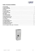
background image

INSTALLATION MANUAL

CW-6S Microcore Indirect Evaporative Cooler

Original English Instructions

Summary of Contents for Climate Wizard CW-6S Microcore

Page 1: ...INSTALLATION MANUAL CW 6S Microcore Indirect Evaporative Cooler Original English Instructions ...

Page 2: ...i ...

Page 3: ...embly 14 Flashing The Dropper 15 Preliminary Cable Installation 15 Weatherseal 16 Installing The Cooler 16 Lifting The Cooler 16 Crane Installation 17 ELECTRICAL REQUIREMENTS Control Module Wiring Diagram 19 Field Wiring Diagram 19 WATER REQUIREMENTS 19 INSTALLING THE DRAIN VALVE 20 CONNECTION TO MAINS WATER 20 WATER HAMMER 20 MAINS CABLE CONNECTION 21 MAINS AND COMMUNICATION CABLE PATH 21 WALL CO...

Page 4: ...essential element that should be conducted before the commencement of work to identify and eliminate the risk of falls or to minimise these risks by implementing control measures There is no need for this to be a complicated process it just is a matter of looking at the job to be done and considering what action s are necessary so the person doing the job does not injure themselves This should be ...

Page 5: ... in brackets ILL2679 A ILL2676 A TOP ISO ILL2680 A ILL2677 A ILL2675 A FRONT SIDE SERVICES UNDERSIDE 1160mm 45 1 2 1160mm 45 1 2 1020mm 40 ILL2678 A 8 3 8 0 570 22 4 suits 530 20 9 dropper suits 530 20 9 dropper 565 22 2 Inlet Inlet Drain Drain CW Logo location 13 6 212 346 212 230 9 0 ...

Page 6: ...RI SUPPLY MICROCORE 1 25 562094 FAN SUPPLY MICROCORE 1 26 562186 MOUNT MOTOR SUPPLY MICROCORE 1 27 562056 VENTURI EXHAUST MICROCORE 1 INDEX PART No DESCRIPTION QTY 28 122342 FAN EXHAUST CW 6S 1 29 562476 CAP FAN CW 6S 2 30 863832 PLUG VENTURI MICROCORE 1 31 863665 STRAPS RETENTION MANIFOLD 1 32 866512 CHLORINATOR LARGE ASSY 1 33 560294 COVER CHLORINATOR MOUNT 2 1 34 560287 FITTING ELBOW AIR BREAK ...

Page 7: ...PTION QTY 14 117935 MICROCORE DIRECT ENCAPSULATION 1 15 122151 ENCAPSULATION INDIRECT RIGHT 1 17 122366 SPREADER SUB ASSY DIRECT CW 6S 1 18 122144 SPREADER SUB ASSY INDIRECT 1 19 562124 SPREADER ELBOW CLIP MICROCORE 1 20 863208 O RING BS112 2 ILL2982 A EXPLODED VIEW ...

Page 8: ...eration Maintenance 1 5 850764 Flexible Water Inlet Hose 1 6 583020 Grommet for Dropper 1 7 639381 T Washer 4 8 101713 Adapter Drain Fitting Assembly 1 9 639391 Solenoid Cover 1 10 122328 Dropper Transition Assembly 1 11 875392 Dropper TEK Screw Fasteners Screw TEK Hex Steel 12 Gauge 30 35mm x 14TPI 20 for dropper 2 for solenoid cover 22 ILL2554 A COOLER INSTALLATION COMPONENTS ILL3397 A ...

Page 9: ...ADEQUATE ROOF STRUCTURE TO BEAR THE LOAD OF ITS OPERATING WEIGHT IT IS LIKELY THAT MOST RESIDENTIAL STRUCTURES WILL REQUIRE REINFORCEMENT Engineering designs of roofs including the supporting structure and cladding should take into account whether the work practices necessary to carry out the installation and maintenance of the roof can be carried out safely Model Shipping Weight Operating Weight ...

Page 10: ...way from adjacent solar panels or similar roof mounted fixtures 5m 17 from a sewer vent and 600mm 2 from a wall ILL2970 A ILL2962 A Allow adequate access to and around the cooler for maintenance Provision must be made for access to electricity water supplies and drains Note Do you need to discuss the installation of items like safety anchor points with the customer The cooler must be mounted at le...

Page 11: ... supplied Use ONLY Belimo LM24A LM24A T or LM24A 90 T damper models STEP 1 ASSEMBLE THE HEAT COOL SWITCH ENCLOSURE Open the enclosure and take note of output positions on the circuit board for 24V damper wiring not supplied ILL2991 A INSTALL THE HEAT COOL DUCT SWITCH OPERATION The Climate Wizard CW 6S is available as a Stand Alone cooling solution or as a Dual System heating and cooling package CW...

Page 12: ...N and cooler CONTROL OUT connections are SELV circuits and shall only be connected to the corresponding SELV circuits on the wall controller and heater control Wall Controller Options Option P N Description Qty A 094298 MagIQtouch Wall Control 1 B 118369 MagIQtouch Wi Fi Smart App Controller 20m Cable 1 A B OR CONTROLLER CABLE VERSION 20M CONTROLLER CABLE VERSION MAGIQTOUCH WIFI SMART APP CONTROLL...

Page 13: ...B 118369 MagIQtouch Wi Fi Smart App Controller 20m Cable 1 ILL3074 B 20m A B OR CONTROLLER CABLE VERSION 20M CONTROLLER CABLE VERSION MAGIQTOUCH WIFI SMART APP CONTROLLER 20M 20M A B HEAT COOL DUCT SWITCH HEATER DAMPERS COOLER DAMPERS CW 6S ILL3074 A COMBINED COOLER AND HEATER WITH A COMMON ZONE AND UP TO 4 ZONES Additional Kits Required P N Description Cable Inc Qty 094939 MagIQtouch Zone Control...

Page 14: ...agIQtouch Wall Control 1 B 118369 MagIQtouch Wi Fi Smart App Controller 20m Cable 1 Gas Ducted Heater Optional Cooling ILL3075 20m A B OR CONTROLLER CABLE VERSION 20M CONTROLLER CABLE VERSION MAGIQTOUCH WIFI SMART APP CONTROLLER 20M 20M A B 20m HEATER DAMPERS HEAT COOL DUCT SWITCH COOLER DAMPERS CW 6S ILL3075 A Additional Kits Required P N Description Cable Inc Qty 094939 MagIQtouch Zone Control B...

Page 15: ...x containing the dropper transition assembly fittings and all associated fasteners Begin by dismantling the dropper transition assembly on the ground For accessibility purposes it is best to temporarily remove the Weatherseal as shown ILL2775 A Fit the transition onto the dropper as shown Ensure that it is orientated correctly as shown by the engraved detail on the transition Fix the transition to...

Page 16: ...iece of rigid material Level the dropper with a spirit level placed across the top of the transition in both directions Once level secure the dropper to the roof structure with a preliminary fastener these are not provided use a regular fastener i e a single nail or TEK screw to assist with holding the dropper in place Recheck the position of the dropper using the spirit level and the height templ...

Page 17: ... through the dropper that are 4mm in diameter This must be completed before lifting commences DO NOT DRILL ANY OF THE PROVIDED 12g TEK SCREWS INTO THE DROPPER AT THIS STAGE THESE ARE FOR USE LATER IN THE INSTALLATION Pass the non taped end of the control cable up into the dropper duct through the grommet Pull the cable through and position it in the transition slot where the sticker markers are Le...

Page 18: ...re drilled and communication cable is protruding from the dropper 1 5m 60 The ideal method of installation will be specific to each assignment To determine which method is best suited to your installation be sure to consider regulations location access points safety and potential obstacles Discuss with the customer LIFTING THE COOLER The CW 6S cooler may be lifted by crane via slinging only Slingi...

Page 19: ...ck to make sure that the white dropper transition straps are visible as shown These straps are flared outwards and should be protruding out from the tank as shown The black foam packaging sling guides beneath the tank have been designed to guide the white transition straps into their positions outside the dropper without fouling on the transition ILL3028 A ILL3030 A ILL3036 B INSTALLATION 3 Place ...

Page 20: ...nsition anywhere The cooler may need to be adjusted while sitting on dropper to achieve this Care must be taken in maneuvering cooler not to dislodge unit or damage any parts of cooler Ensure the communications or mains cables are not trapped or pinched between the dropper and tank Align the dropper transition straps with the pre drilled holes in the dropper T washers Some transition straps may ne...

Page 21: ...RAIN CHLORINATOR SENSOR W CONTROL ILL2681 B ILL2681 B FIELD WIRING DIAGRAM CONTROL MODULE WIRING DIAGRAM WATER REQUIREMENTS Installation of the cooler water supply must conform to local plumbing rules regulations and standards The following specifications for the cooler water supply are required Water Connection BSP Min Water Pressure 100kPa 15psi Max Water Pressure 800kPa 115psi Min Water Flow 13...

Page 22: ...crew the nut 3 up tightly by hand underneath to secure the drain valve Locate the funnel 4 up against the bottom of the drain valve thread and secure with the second larger nut 5 Make sure that you use the correct drain adaptor Make sure the drain water discharge flows freely away from the cooler Important Do not over tighten plastic fittings Secure the Solenoid Cover Plate in place against the co...

Page 23: ...ble tray on the inner wall of the tank and then fed through to the control module Important Ensure the mains cable is not submerged or touching the water in the tank at any point along the cable length Make use of the resealable cable restraints Cable tie to existing looms if necessary 4 Remove the Control Module cover Connect the communications cable to the socket labelled Wall Control Replace th...

Page 24: ... following points must be taken into consideration Avoid direct sunlight exposure Avoid mounting on external walls Avoid mounting the wall control near heat sources such as stoves and televisions Do not locate in the direct airflow of the duct outlets Do not locate in strong drafts or in dead spots such as cupboards drawers Always fill in the cable entry hole Hot air coming through the wall may in...

Page 25: ...acket Alternatively a standard stud mounting bracket used for wall plates can be used with plasterboard walls Insert wall plugs into holes Align and screw the bracket into position using the supplied screws ILL1587 A ILL1597 B ILL1589 A ILL1591 A ILL1590 A ILL1588 A Ø16mm 5 8 Ø5 6mm 13 64 15 64 ILL1597 B Drill a 16mm 5 8 hole for cable access and two smaller holes for the wall plugs provided 5mm 1...

Page 26: ...ng of the wall control We recommend that the cable access hole be sealed but in such a way that the cable can still retreat into the wall cavity ILL1592 A Slide and align the wall control over the protruding bracket tabs Pull the wall control down so the bracket tabs engage and locate with the keyway slots on the rear Step 1 Step 2 ILL1593 A ILL1594 A To activate the MagIQtouch Controller screen p...

Page 27: ... it is suggested that technicians obtain a MagIQtouch Wall Controller as a tool for use during servicing The MagIQtouch Controller provides additional user and technician functions Refer to the installation manual provided with the MagIQtouch Controller for instructions on installing the controller The wall control cable plugs into the electronics module A refer diagram adjacent Coolers are suppli...

Page 28: ... 7 SUPPLY MOTOR ERROR Check Motor Power Cable connections Check Motor Communications Cable connections Fault Code 8 WARM START Mains input voltage is under 93Vac but not low enough to reset the PCB Fault Code recorded when voltage returns to useable level Consult with Building Manager 1 Green Red Flash then 2 seconds off CHLORINATOR PERFORMANCE DEGRADED Chlorinator operating current is less than s...

Page 29: ...ntrol boxes Power supply Motor cable s Control cable Pressure Sensor Hose s Drain valve Solenoid cable Pump cable Probe cable OWNER INSTRUCTIONS The owner has been instructed how they can electrically isolate the unit at the meter box in case of an emergency DUCTWORK DESIGN Adequately sized and positioned balanced run lengths Air directed appropriately INSTALLED Hung lead ins to outlets no kinks o...

Page 30: ...ment replaces water when salinity level reaches set point Timed Drain drains the tank after 8 tank fill cycles or every 65 minutes system dependant No Drain Control salinity control external to electronics eg continuous bleed No Water Thermostatic allows thermostatic control in VENT mode No water present Cooling performance is limited Weatherseal Open Speed The cooler fan will turn on at the speci...

Page 31: ... Adjust motor amp setting if necessary Fan motor burned out Replace motor Low system voltage Consult with power supply authority Check fault condition via the wall control unit or the tri colour LED on cooler electronics module Rectify fault as indicated and restart the cooler Wall Control failed Replace wall control If the wall or remote control is in AUTO or AUTO TIMER mode and no fan bars are d...

Page 32: ...O ACHIEVE A MOISTURE CONTENT NOT EXCEEDING 15 T7 HARDWOOD TIMBER SHALL BE MINIMUM F11 STRESS GRAD U N O SOFTWOOD TIMBER SHALL BE MGP10 U N O T8 ALL CUT SURFACES OF TREATED MEMBERS SHALL BE RE TREATED ON SITE TO ACHIEVE ORIGINAL HAZARD CLASS IN ACCORDANCE WITH AS1604 T9 TIMBER EXPOSED TO VIEW SHALL BE DRESSED PLANED ALL ROUND T10 EXTERNAL TIMBER IN BUSH FIRE ZONES MUST BE SEASONED HARDWOOD AS DEFIN...

Page 33: ...NING AND VENTILATION TO MINIMIZE HAZARDS TO PERSONNEL IF SITE BASED TREATMENT IS UNAVOIDABLE SID19 TRY TO AVOID WORKING IN CONFINED SPACES IF CONFINED SPACES WORK CAN T BE AVOIDED PROVIDE A SAFE WORK METHOD STATEMENT ADDRESSING MITIGATION OF RISKS PROVIDE ADEQUATE SIGNAGE TO TEMPORARY AND PERMANENT CONFINED SPACES TO AS2865 SID20 AVOID HOT WORKS ON SITE PARTICULARLY IN TIMBER FRAMED STRUCTURES HOT...

Page 34: ...R OF DROPPER TYPICAL SCREW LAMINATION DETAIL SCALE 1 20 NOTES 1 600mm SPACED TRUSSES ASSUMED TO SUPPORT TILE ROOF 2 DIMENSIONS OF A C UNIT AND DROPPER MAY VARY TO SUIT ROOF SLOPE 3 0 0 SCREWS ALTERNATE SIDES BEAM WIDTH MIN SCREW GAUGE MIN SCREW LENGTH 45 No 14 75mm 35 No 14 75mm BEAD OF ELASTOMERIC ADHESIVE AROUND PERIMETER OF JOIN BEAM WIDTH MIN NAIL GAUGE MIN NAIL LENGTH 45 3 30mm 90mm 35 3 06mm...

Page 35: ...ING TRUSS S T 1 NOTES 1 1200mm SPACED TRUSSES ASSUMED TO SUPPORT SHEET ROOF 2 DIMENSIONS OF A C UNIT AND DROPPER MAY VARY TO SUIT ROOF SLOPE TYPICAL SCREW LAMINATION DETAIL SCALE 1 20 3 0 0 SCREWS ALTERNATE SIDES BEAD OF ELASTOMERIC ADHESIVE AROUND PERIMETER OF JOIN PRYDA MINIGRIP 2 35x3 15Ømm NAILS OR SIMILAR INTO EACH MEMBER B 1 BEAM WIDTH MIN SCREW GAUGE MIN SCREW LENGTH 45 No 14 75mm 35 No 14 ...

Page 36: ...CHEDULE MARK SIZE REMARKS TR1 C10012 TRIMMER ST1 C10012 STRUT FIX TO TOP CHORD AND STEEL DROPPER WITH 2 12g TEK SCREWS PROVIDE 1 STRUT EACH SIDE OF DROPPER ADDITIONAL C10012 AS NOTED T R 1 IF GAP EXISTS BETWEEN DROPPER AND MEMBERS PROVIDE TIMBER PACKING TO SUIT MAX THICKNESS OF PACKING TO BE 50mm REINSTATE ROOF SHEETING AND FIX TO TRIMMERS PROVIDE ADEQUATE FLASHING AROUND DUCT DESCRIPTION DATE DRA...

Page 37: ...C UNIT AND DROPPER MAY VARY TO SUIT ROOF SLOPE 1200 MIN B 1 PROVIDE TIMBER WEDGE TO SUIT ANGLE OF STRUT PROVIDE TIMBER PACKING BETWEEN STRUT STEEL DROPPER AS NECESSARY TEK SCREWS NOT TO BE INSTALLED WITHIN 50mm OF CORNER OF DROPPER IF GAP EXISTS BETWEEN DROPPER AND MEMBERS PROVIDE TIMBER PACKING TO SUIT MAX THICKNESS OF PACKING TO BE 50mm REINSTATE ROOF SHEETING AND FIX TO TRIMMERS PROVIDE ADEQUAT...

Page 38: ... IF EXISTING WALL IS TIMBER USE EXISTING TOP PLATE REINSTATE ROOF SHEETING AND FIX TO TRIMMERS PROVIDE ADEQUATE FLASHING AROUND DUCT ALL TIMBER MEMBERS TO BE CONNECTED WITH MINIGRIP UNO IS ACCORDANCE WITH MANUFACTURERS SPECIFICATIONS ST1 2 No 12 TYPE 17 SCREWS NOTCH ST1 TO SUIT WIDTH AND DEPTH OF TR1 TYPICAL ST1 TO TR1 SCALE 1 10 45 90 TR1 DESCRIPTION DATE DRAWING SCALE DRAFTER ENGINEER MANAGER DR...

Page 39: ...d in containers for safe keeping Initial disassembly on the ground 1 Remove the plastic packaging film from the cooler along with the vertical wooden support members for transport Dispose of each responsibly 2 Remove all 8 side panel clips all 4 top clips and all 4 side panel assemblies This will require a flat head screw driver Store the clips in a container ILL2788 A 3 Remove the lid grille by l...

Page 40: ...81 B ILL2681 B 5C Remove any cable ties above the enclosure to free the 2 cables to the top exhaust motor then free these cables Remove the single centre screw holding the electronics enclosure to the mount plate Remove the electronics enclosure splash cover Leave any remaining wires and hoses connected within the electronics enclosure Rest the electronics enclosure on the tank in a drained and dr...

Page 41: ...le tie that is loosely constraining the cables to the inner plenum 6 If you have successfully freed the top motor cables you will be able to lift the top motor fan assembly out from the top of the cooler by lifting it up vertically ILL2797 A Important This assembly weighs approx 22kg Use the appropriate mechanical aids and lifting technique to avoid injury Set this assembly aside ILL3120 A ILL3115...

Page 42: ...ition the vertical hose pillars so that they are resting inside of the tank where they are out of the way ILL2801 B ILL2801 B ILL3123 A Lift the assembly up and set aside Do not disassemble the foam from the inner plenum ILL3124 A COOLER READY TO LIFT DO NOT BREAK DOWN ANY FURTHER Transporting the cooler to the roof Caution Do not take risks when raising the cooler to the roof for installation Use...

Page 43: ...e cooler with care If you intend to pull the cooler onto the roof using a ladder as a slide then guide the cooler on the underside of the tank Important This assembly is bulky and weighs approx 35kg 13 With a minimum of two persons transport the bottom half of the cooler to the roof Important It is best to leave all other components and assemblies on the ground until they are required in order to ...

Page 44: ...te mechanical aids and lifting technique to avoid injury The assembly is keyed to ensure the motor cable exits to the correct orientation in the cooler Reinstall electronics enclosure in its original position and secure with the clips and screw 24 Install top motor fan assembly to the top of the plenum in reverse order of that specified in step 5 Ensure cables are oriented towards the electronics ...

Page 45: ...ter to form a good sealing face Handle the manifolds with care Excessive force may damage the foam and or manifold assembly ILL3127 A 35 Secure the manifold assemblies by pulling and locking the lower and upper manifold retention straps into the dedicated slots on the manifolds ILL2814 A 36 Reconnect the vertical hose pillars to the hose restraint clips on the foam plenums ILL2815 A APPENDICES 30 ...

Page 46: ...ws uniformly and adequately 39 Transport the side panel assemblies to the roof To reinstall all 4 side panel assemblies rest the bottom lip of the side panel on the tank guide ribs and engage the clips on an angle as shown Mate the top edge of the side panel with the lid and press fit along the top surface The panel will lock into place with the lid For installation of successive side panels ensur...

Page 47: ...CW 6S INDIRECT COOLER INSTALLATION MANUAL 45 NOTES ...

Page 48: ...ions Please contact your local distributor seeleyinternational com MANUFACTURED BY SEELEY INTERNATIONAL PTY LTD 112 O SULLIVAN BEACH RD LONSDALE SA 5160 AUSTRALIA IMPORTED BY SEELEY INTERNATIONAL EUROPE LTD UNIT 11 BYRON BUSINESS CENTRE DUKE STREET HUCKNALL NOTTINGHAM NG15 7HP UNITED KINGDOM SEELEY INTERNATIONAL AMERICAS LTD 1002 S 56TH AVENUE SUITE 101 PHOENIX ARIZONA 85043 USA SEELEY INTERNATION...

Reviews:

Related manuals for Climate Wizard CW-6S Microcore