Sears Craftsman EZ3 917.259553, Owner'S Manual
The Sears Craftsman EZ3 917.259553 owner's manual is essential for maximizing the potential of this powerful tool. Easily download the detailed manual for free from our website, allowing you to effortlessly navigate through important instructions and insightful tips. Unlock the full potential of your Craftsman EZ3 with this essential download.
Share
Download


Reviews:
No comments
Related manuals for Craftsman EZ3 917.259553

357-344M
Brand: Land Pride Pages: 62

127-335-300
Brand: MTD Pages: 16

36 / 968999539
Brand: Dixon Pages: 48

FZR 2025-E
Brand: Fieldmann Pages: 24

HRG416C1 PKEH
Brand: Honda Pages: 56

ME 443
Brand: Viking Pages: 284

Super Surfer II GSKA1948S
Brand: Great Dane Pages: 78
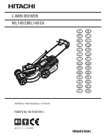
ML140E
Brand: Hitachi Pages: 25

ML190EA
Brand: Hitachi Pages: 100

ML 40SR
Brand: Hitachi Pages: 160

RPM 56 S-MS
Brand: Royal Pages: 52

LM315GC
Brand: Baroness Pages: 86

917.272930
Brand: Craftsman Pages: 56

917.272921
Brand: Craftsman Pages: 56

917.272912
Brand: Craftsman Pages: 56

917.272954
Brand: Craftsman Pages: 60

917.272953
Brand: Craftsman Pages: 60

917.272951
Brand: Craftsman Pages: 60


