Sears Craftsman 944.603900, Manual
The Sears Craftsman 944.603900 is a reliable and high-quality power tool designed to make your DIY projects a breeze. With this versatile machine in your hands, you can effortlessly tackle any task. To fully utilize its potential, simply download the free user manual from manualshive.com and unlock its full capabilities.
Share
Download


Reviews:
No comments
Related manuals for Craftsman 944.603900

KM 402
Brand: K&M Pages: 9
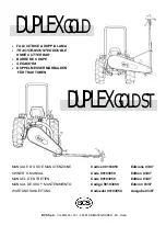
DUPLEX GOLD
Brand: BCS Pages: 34

TCW-7055
Brand: Washtech Pages: 30

148-860A
Brand: MTD Pages: 28

148-760A
Brand: MTD Pages: 28

144-918-000
Brand: MTD Pages: 36

TG Series
Brand: New Holland Pages: 36

Esco ULTRAEDGE
Brand: Weir Pages: 12

65E Turbo Motor Grader
Brand: NorAM Pages: 830

Agri-Fab 45-0302
Brand: SpeedEPart Pages: 8

Groom Master II 88009
Brand: Jacobsen Pages: 104

DCF100-45E7
Brand: Kalmar Pages: 88

TC607X2
Brand: Jenn-Air Pages: 196

21-KG08
Brand: Kellfri Pages: 16

4KUCS181T
Brand: KitchenAid Pages: 39

Proxima Plus 100
Brand: Zetor Pages: 34

Proxima Plus 105
Brand: Zetor Pages: 197

PROXIMA PLUS 100 2012
Brand: Zetor Pages: 212


