TORG
is composed by an aluminum pressure die-cast monobloc, into which
reduction gears are contained. If there is an obstacle in front of the gate while it is
moving, the
mechanical clutch
guarantees the
anti-crushing safety
.
In case of power supply or servicing lacking,
TORG
has a release system which
allows the uncoupling of the gears in a rapid and easy way through a key
supplied with the operator.
The limit switch is of mechanical type.
The electronic managing equipment together with the
encoder
(optional fitting
purchasable separately) keeps control on all the functions of the automation
system and on the reversing of the movement in case of obstacle.
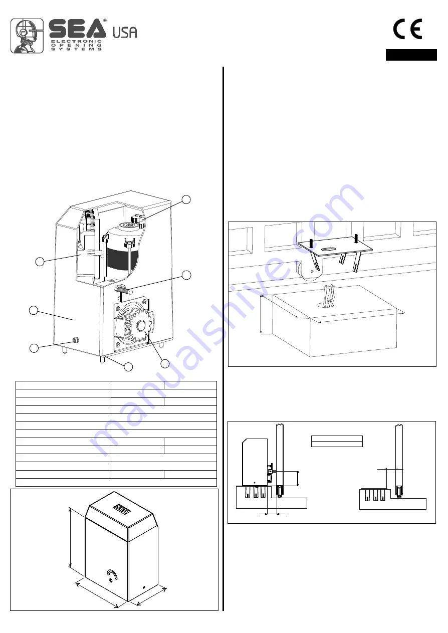
1
Mounting plate
2
Pinion
3
Mechanical limit switch
4
Encoder
TECHNICAL DATA
Power supply
Power
Motor rotation speed
Reduction ratio
Room temperature
Thermal protection intervention
Weight of the unit
Capacitor
Protection rating
Gate speed
Maximum weight of the gate
Mechanical limit switch
Torg 600 Torg 800
115 V (±5%) 50/60 Hz
320 W 340 W
1450/1720 rpm
1/32
-4°F +131°F
266°F
29,7 Pound 30,8 Pound
45uF 60uF
IP44
32,8 feet/min
1323 Lbs 1764 Lbs
REV 02 - 09/2008
5
Electronic control unit
6
Carter
7
Fixing carter screw
MAIN PARTS NOMENCLATURE
1. GATE ARRANGEMENT
The first thing to check is that the gate is in good running order as follows:
a) The gate is rigid and straight and runs smoothly throughout its travel.
b) The lower track is in good order, straight and levelled.
c) The lower support wheels have sealed bearings or grease points.
d) The top guide must be manufactured and installed so that the gate is perfectly
upright.
e) Physical gate stops must be fitted to prevent the gate coming out of its guides
and track.
DIMENSIONS
Fig. 1
2. MOUNTING PLATE INSTALLATION
To install the mounting plate it is necessary to:
2.1.
Have a mounting plate manufactured to the dimensions shown in Fig. 1. The
plate will require to have concrete holding into which the foundation plate and the
anchor bolts will be walled up. It is best if the gate structure allows the plate to be
raised up from the finished level by 1,96 in. This will stop water gathering around
the operator.
5
,9
in
,6
n
10
i
1 ,8 i
3
n
TORG
12
n
i
8,
i
85
n
6,1 in
Fig. 2
1,96 - 2,16 in
2.2.
When you are concreting in the plate install any necessary cable ducts (Ø
1,38 in minimum) and cables in through the base plate. Cable ducts should have
sweep bends not elbow ones.
2.3.
When concreting in the plate check that the plate is perfectly levelled and
that the measurement of 1,96 - 2,16 in given in Fig. 2 is followed.
2,16 - 2,36 in
Q
Z16
MINIMUM QUOTA Q
4,4 in
3.
3.1.
Take the carter away unscrewing the screws placed in the two sides of the
motor reducer.
3.2.
Adjust the motor reducer height using the four supplied grains (Fig. 3)
respecting the quotes mentioned in Fig. 2. The adjusting grains can be used to
correct a previous and imperfect levelling of the foundation plate.
3.3.
Fix the motor reducer to the foundation plate with the supplied dices and
washers (Fig. 4)
FITTING OF THE UNIT
FITTING AND CONNECTION INSTRUCTIONS
3
3
4
4
1
1
7
7
2
2
5
5
6
6
ENGLISH
International registered trademark n. 2.777.971