GSM-BGS5-EEN_User_Manual EN v2-02.docx
Strana 1 z 2
GSM-BGS5-EEN
1.
Introduction
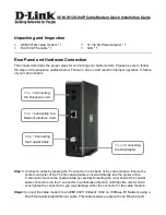
Modem in an industrial metal aluminum case which
is suitable for installation into a control cabinet.
Modem has two communication ports (Ethernet and
USB) with adjustable watchdog. The modem is equipped with a GSM module Gemalto
(Cinterion) BGS5 rel.2. Thanks to standard Ethernet and USB interface, the modem is
suitable for fast implementation in devices that require remote communication.
The modem has JAVA OPEN PLATFORM in which you can write your own program, for
example a program for downloading and sending data from connected technology.
Etherner interface is implemented as a converter from RS232 to Ethernet.
In factory default, DHCP sever assigns dynamic IP address, name:
admin
,
password:
admin
.
2.
Package Content
1pc GSM modem
1pc 2-pin connector 3,5mm
3.
Recommended Accessories
3.1
Antenna
GSM-ANT11K
2dB, Whip jointed antenna, without cable
GSM-ANT01S
5dB, magnetic, cable 3m
GSM-ANT51S
9dB, magnetic, cable 3m
GSM-ANT07S
9,5dB log–per, cable 10m
3.2
Power Supply
GSM-PWR12
Power supply adapter into socket 230V
AC
/ 12V
DC
, 1A
GSM-PWR1
DIN rail mounted supply module 230VAC / 12VDC, 1.25A
Note: for DIN rail mounting inside of a cabinet suitable:
GSM-75-DIN
Plastic DIN rail holder or
GSM-ZIP50
Industrial 3M Dual-Lock ZIP 25x50mm for wall mounting
3.3
Cables
HW-11.99.8752
USB 2.0 AB (micro USB to a modem), length 1.8m
4.
Technical Specification
Parametr
Symbol
MIN.
TYP.
MAX.
Unit
Power Supply
(PWR)
Voltage DC
7 V
DC
8 to 30
33 V
V
DC
Standby power.
consumption
Max. power.
consumption
connected to
GSM network
(call o GPRS)
0,84 (70mA for 12 V
DC
)
2.1
W
W
POWER
supply conn.
2-pin removable screw terminal block, pitch 3.5 mm (PWR),
or micro USB connector
Power supply
via USB **
Voltage
Current
5
300
500
V
mA
Ingress
Protection
IP
40
Temperature
Storage
tSTG
-40
+85
°C
Operating
tA
-30
+65
°C
Humidity
Operating
95
% R.V.
Dimensions
Width
W
54
mm
Height
H
24
mm
Length
L
82
mm
Weight
0.103
kg
Note: If the power supply and USB connectors are connected at the same time, current
goes only from power supply connector PWR.
** As the power consumption from USB is higher than 500mA, it is sometimes needed to
reserve the current or use powered USB hub.
5.
Modem Parameters
Parameter
Description
GSM , GPRS 12
850/900/1800/1900 MHz
(GPRS 85.6 kbps DL, 85.6 kbps UL)
Antenna connector
Device - SMA (F), 50 Ohm
Internet services
TCP/UDP server/client, DNS, Ping, FTP client, HTTP client
JAVA
2 MB RAM and 4 MB Flash File System
USB 2.0
Micro USB; USB2.0
Ethernet
Connector RJ45
HW watchdog
See the chapter Watchdog setting
6.
Documentation
For
USB driver
, a list of
AT
commands
and other information, visit the
www.seapraha.cz
, type “GSM-BGS5-EEN” into the search box.
In the Name field, enter the text
sea
. In the Password box, type
siemens
.
If you are using WIN10 and you will use only control via AT commands, do not
download the driver, WIN10 will install its own driver automatically.
7.
Hardware
7.1
Power supply and indication LEDs
Supply voltage is connected to terminals PWR and must be in the range of 7-33 V
DC
.
The device is protected against overvoltage and has a built-in refundable SMD fuse. If
the external fuse is needed, use 1.25 A fuse at V
CC
line. As the power consumption from
USB is higher than 500mA, it is sometimes needed to reserve the current or use powered
USB hub.
The modem can be powered directly from the USB connector. If the power supply and
USB connectors are connected at the same time, current goes only from power supply
connector PWR.
LED PWR is located on the bottom-right side of PWR connector, LED ETH is located
bottom-left side of Ethernet connector.
LED
COLOR
MEANING
PWR
green
dark
… device is not supplied, or internal power
convertor is out of order
light
… device in operation state
RS232
yellow
Blinking
… communication from the GSM module
into Ethernet module
7.2
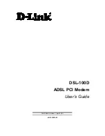
NANO SIM card reader and GSM state indication
Insert the nano SIM card into the holder (cut corner first, contacts
up - towards the inscription SIM). The correct insertion is indicated
by mechanical click noise. Push gently and release to remove the
SIM card.
Above the SIM card holder is located the LED which indicates status of GSM.
LED
COLOR
MEANING
Located
above SIM
card holder
SIM
blue
Device state indication.
Dark
… device failure; Device was switched of using
AT command
blinking 1:1
… device starting up
1 short blink per 4 seconds
… device operational
7.3
Antenna
The antenna is connected via SMA connector. The device is fitted with SMA female. The
connected antenna must have SMA male. The impedance is 50 Ω.
7.4
Communication ports (Ethernet and micro-USB)
To communicate with the modem (AT commands) is designed interface Ethernet and
USB. The device includes a connector Ethernet RJ45 and micro-USB.
Ethernet module you can set via webserver which is included in Ethernet module (In
factory default, DHCP sever automatically assigns dynamic IP address, name:
admin
,
password:
admin
.
Ethernet module is internally connected to GSM module instead of RS232 interface.
Baud rate for USB is not needed to set.
You will see two COM ports in WIN Control panel. For sending AT commands you must
use the port, which you find in Device Manager „Modems“ (Parameters/Modem). Other
port is determined for JAVA application´s development.
7.5
DIN rail mounting
If you need to place the device into the switchboard on DIN rail, screw the plastic holder
GSM-75-DIN drilled hole in the side of the modem.
8.
Warranty
General warranty period is 24 months after purchase, when eventual malfunction device will be repaired free of charge in
SEA spol. s r.o. while shipping to SEA is paid by customer and SEA pays for shipping back to customer.
The warranty does not cover any damage caused by wrong use which does not comply the technical specifications and
user instructions and any accidental damage (e.g. by water, lightening etc.).
SEA spol. s r.o. has NO RESPONSIBILITY for any damage, lost, costs and any other problems direct or inducted, caused
by device malfunction from any reason.
In case of incompleteness or any damage in the packaging it is necessary to inform SEA spol. s
r.o. immediately (within five days).
CE Declaration of conformity
in accordance with the Radio and Telecommunications Terminal Equipment Directive
1999/5/EC (R&TTE) and Directive 2011/65/EU (ROHS).
We
SEA, spol. s r.o., Dolnoměcholupská 21, CZ 102 00 Praha 10,
ID
: 47117931
(
manufacturer
)
declare under our sole responsibility, that product
GSM modem with Ethernet a
USB
type
GSM-BGS5-EEN
is in conformity with the following standards:
health and safety:
EN 62368-1:2015 + Opr.1:2016 + A11:2017
EMC:
EN 301489-1 v2.1.1 EN 301489-52 v1.1.0
radio frequency:
EN 301 511 v 12.1.10
Place of issue:
Praha
Name:
Ing. Vladimír Rosůlek
Date of issue:
19.7.2018
Grade:
director