background image

ASTRA  1000RS

SERIES

AUTOMATIC/MANUAL TRANSMISSION

WITH SEPERATE LOCK/UNLOCK BUTTONS

REMOTE START SYSTEM

PRODUCT MANUAL

Summary of Contents for Astra 1000RS Series

Page 1: ...ASTRA 1000RS SERIES AUTOMATIC MANUAL TRANSMISSION WITH SEPERATE LOCK UNLOCK BUTTONS REMOTE START SYSTEM PRODUCT MANUAL ...

Page 2: ...year if required for repair and or replacement of any defective parts A copy of the original purchase and installation receipt must accompany any products returned for warranty service Warranty is limited to defective parts and or replacement parts only and excludes any incidental and consequential damages connected therewith The manufacturer of this theft deterrent system makes no warranty agains...

Page 3: ...e 9 Shut Down Page 10 Quick Stop Page 10 Automatic Start Mode Page 10 5 Extended Features Page 11 Ignition Door Locking Page 11 Ignition Door Unlocking Page 11 Auxiliary Function Outputs Page 11 Turbo Timer Feature Page 11 Call Feature Page 11 6 System Installation Page 12 Mounting the Control unit Page 12 7 System Wiring Page 13 5 Pin Starter Harness Page 13 16 Pin Main Harness Page 13 4 Plug in ...

Page 4: ......

Page 5: ...ote started the Astra Starter employs several safeguards In the event the brake pedal is pressed while the engine is remotely running the remote start will immediately shutdown to prevent unauthorized users from attempting to drive the vehicle The system is equipped with a hood pin input to prevent access to the engine compartment while the vehicle is remotely running Finally the Valet Mode preven...

Page 6: ...is pressed and held the LED will flash a number of times to indicate from which page it is transmitting Under normal operation only pages 1 and 3 are used Page 1 is the default page and operates lock unlock aux and remote start Page 3 press side button 2X is used for Two Car Operation see page 3 Other pages and channels may be used in the future Adding Replacing Transmitters To replace lost or sto...

Page 7: ...e first vehicle in the manner described above Program transmitters C and D by pressing the Shift button twice before performing steps 3 and 4 above When finished programming the first vehicle program transmitters C and D into the second vehicle as normal then program transmitters A and B by pressing the Shift button twice before performing steps 3 and 4 above When programmed in this manner the dri...

Page 8: ...tem is in Valet Mode Button 2 Unlocks the system Button 3 Activates the Auxiliary 1 output normally used for trunk release note trunk icon on button Button 4 Activates the Remote Start Function Button 5 is the Confirmation and Programming button Quickly pressing button 5 will activate the LCD display s backlighting for use in the dark Pressing button 5 for 2 seconds activates the system s confirma...

Page 9: ...lody to indicate the time has been set Setting The Alarm Clock The alarm clock function can be set to play an alert melody at a specific time of day To set the alarm clock function 1 Press and hold Buttons 2 and 3 until the remote beeps three times The alarm clock bell and three bars will be shown indicating alarm clock set mode is entered 2 Press Button 2 until the desired hour is displayed 3 Pre...

Page 10: ...ss and hold Button 5 until the display shows CON The transmitter will beep once 2 Release Button 5 The transmitter will beep once The icons representing current system status will be displayed on the LCD panel Transmitter Programming Pressing and holding transmitter button 5 will scroll through several transmitter programmable options that may or may not be available depending on the model of syst...

Page 11: ...Astra 1000RS Series Page 7 Transmitter Icon Description Some of the features in the LCD s Icon Description page are not Available on the 1000RS Series ...

Page 12: ... a crowded parking lot Look for the flashing parking lights which should be your vehicle To activate the Visual Car Locator Mode 1 Press and hold Button 1 for 3 seconds The parking lights will flash The doors will unlock allowing access to the vehicle 2 Press Button 2 to turn off Car Finder Valet Mode The Valet Mode temporarily disables the remote start system so the vehicle may be serviced by a m...

Page 13: ...n Valet Mode 2 Press and hold Button 4 The parking lights will turn on The engine will start and run for the duration of its programmed Run Time The heater or air conditioner will turn on if turned on prior to exiting the vehicle If the engine fails to start on the first attempt it will repeat the starting procedure 2 more times If the vehicle fails to start after a total of 3 times the parking li...

Page 14: ...ly or by using the Remote Transmitter To resume control of the vehicle 1 Unlock the doors manually or with the Transmitter 2 Turn on the ignition 3 Press the Brake Pedal to disengage the remote start If optional keyless entry feature is installed Automatic Start Mode The Automatic Start Mode allows the vehicle to automatically start the vehicle every one or two hours and run for the preset Run Tim...

Page 15: ...cles with turbocharged engines to remain running after the ignition key is removed for proper cool down of the turbocharger The Turbo Timer feature requires connection to the vehicle s parking brake wire and is compatible with most gasoline powered engines and diesel engines where a glow plug connection is not required To activate the Turbo Timer feature 1 Leave the engine running after parking th...

Page 16: ...r the installation 9 Always use a Volt Ohm meter for testing vehicle circuits Never use a test light 10 Always look before drilling any holes or mounting self tapping screws Be sure fuel lines and exterior wiring looms are clear as they are often close to the chassis and difficult to see 11 Protect all wires running from the engine compartment to the interior of the vehicle by covering with electr...

Page 17: ...oltage must not drop when the car is starting Pin 7 WHITE BLACK WIRE Hood Pin Input Connect the to the hood pin switch The switch must provide a ground output when switch is opened Pin 8 BLACK WIRE Ground Input The Black wire must connect to a solid chassis ground Clean away any paint or dirt to insure the best possible ground Pin 9 VIOLET WHITE WIRE Factory Rearm Output 500 mA The White violet wi...

Page 18: ...A trigger output for optional plug in door lock relay module GREEN WIRE negative lock output 500mA 4 Pin White Connector WHITE WIRE Parking Brake Input For Manual Transmission and or vehicles equipped with a turbo charged engine Must be connected if using the Turbo Timer feature and or Manual Transmission remote start feature BLUE WIRE Auxiliary start activation Input Pulsing this wire to ground w...

Page 19: ...t polarity jumper will be visible next to the parking light relay Set the jumper for the correct polarity output as described below then reassemble the main unit case Parking Light Output Selects the polarity for the output of the on board Parking Light relay Left Pin Center Pin positive Right Pin Center Pin negative Jumper Settings default setting shown ...

Page 20: ...ettings The Valet Mode is off 3 Turn off ignition Programmable System Options The following is a description of the programming options of the system Some of the program branches control more than one option and may require accessing a particular branch number twice in order to program all desired features 1 Ignition Door Locking Selects whether or not the system will automatically lock the doors ...

Page 21: ...hicle s tachometer Tachless operation may not be compatible with some vehicles or in severe temperatures in which case the tach wire must be connected 13 Remote Start Program This dual program branch sets the engine mode for Gas or Diesel and learns the vehicle s RPM threshold Learning the RPM threshold automatically selects the RPM monitor mode For installation into a diesel equipped vehicle firs...

Page 22: ...und upon start 21 Horn Chirp When Enabled horn and siren chirp When disbled only siren chirps Branch Feature Button 1 default Button 2 Button 3 1 Ignition Door Locking Enabled Disabled 2 Ignition Door Unlocking Enabled Disabled 3 Door Unlock Pulse Single Double 4 Door Lock Pulse Length 1 second 3 seconds 0 1 Sec 5 Aux 1 Mode Pulsed Timed 10Sec Latched 6 Unlock with Aux 1 Disabled Enabled 7 Start i...

Page 23: ...ger Reverse Polarity Vacuum Adding Actuators Follow the diagrams below for connecting basic door lock systems For Two Stage door lock systems separately unlocks driver and passenger doors see following pages Door Lock Diagrams Relay Diagrams Starter Anti Grind ...

Page 24: ... Operation is subject to the following two conditions 1 This device may not cause harmful interference 2 This device must accept any interference received including interference that may cause undesired operation Technical Information Wiring Diagram Clutch Switch Override Diagrams Manual Trans ...

Page 25: ...Astra 1000RS Series Page 21 Notes ...
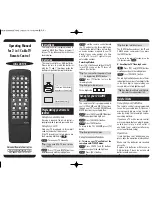
Page 26: ...Page 22 Astra 1000RS Series Notes ...

Page 27: ...Astra 1000RS Series Page 23 Notes LED Light LED Light Call Valet Override Switch Valet Override Switch RS 2W Series RS Series ...

Page 28: ...put Black Gray Tach Input RPM Input Brown Siren Output 3Amp Green Negative Door Input Violet Positive Door Input Yellow 12V Ignition Input White Black Hood Pin Input Black Sytem Ground Black White Dome Light Factory Rearm Out 500ma White Violet Factory Disarm Out 500ma Blue Orange Ground When Running Out 500ma Orange Anti Grind Out 500ma Gray Trunk Release Out 500ma Green White Brake Input White P...

Reviews: