background image


Installation and commissioning manual 

Wireless Data System  

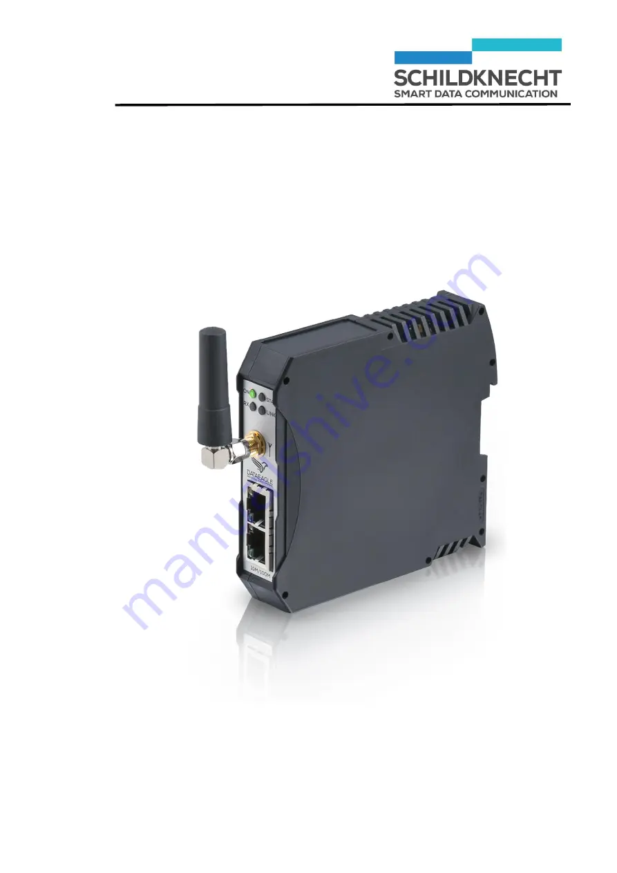
DATAEAGLE® 4XXX Compact 


Schildknecht  AG 

D -71711 Murr 

– Haugweg 26 

Tel +49 (0)7144 89718-0 - Fax +49 (0) 7144 8971829     

Email: [email protected] - Internet: www.schildknecht.ag


DATAEAGLE 4XXX Compact  

Version: 14.04.2020


Summary of Contents for DATAEAGLE COMPACT 4 Series

Page 1: ...anual Wireless Data System DATAEAGLE 4XXX Compact Schildknecht AG D 71711 Murr Haugweg 26 Tel 49 0 7144 89718 0 Fax 49 0 7144 8971829 Email office schildknecht ag Internet www schildknecht ag DATAEAGLE 4XXX Compact Version 14 04 2020 ...

Page 2: ...tion For this reason no claims re lating to the aforemen tioned may be derived from the information illustration and descrip tions provided in these operating instructions for appliances or systems manufactured after the date of issue of these op erating instructions Warranty Schildknecht AG can ac cept no liability for indi rect damage or direct damage incidental dam age consequential dam age or ...

Page 3: ...y We show you step by step how to install the system put it into operation and how to operate it Any questions First have a look in the table of contents You will quickly find what you are looking for If you do need us in person just call us or send a fax Schildknecht AG Haugweg 26 D 71711 Murr Phone 49 0 7144 89718 0 Fax 49 0 7144 8971829 Internet www schildknecht ag e mail office schildknecht ag...

Page 4: ...3 2 4 Installation of new devices 4 1 4 1 Overview Installation 4 1 4 2 Install unit on top hat rail 4 2 4 3 Install antenna cable 4 3 4 4 Connect Ethernet plug 4 4 4 5 Connect power supply 4 4 5 Extension and exchange 5 1 5 1 Preparation 5 1 5 1 1 System requirements 5 1 5 1 2 Create a new folder 5 1 5 1 3 Microsoft Internet Explorer 5 2 5 1 4 Install USB drivers 5 3 5 1 5 Install Dataeagle Wizar...

Page 5: ...6 1 Function 6 1 6 2 Setting of the filter time at Radio Master and Radio Slave 6 1 6 3 Typical values for the filter time 6 5 6 3 1 Default 6 5 6 3 2 Recommendation for operation 6 5 6 3 3 Recommendation for commissioning 6 5 6 3 4 Recommendation for applications with Profisafe 6 5 7 Dismantling and disposal 7 1 8 Tips and Tricks 8 1 8 1 Improving the EMC safety 8 1 8 1 1 Introduction 8 1 8 1 2 B...

Page 6: ... followed by a description about how the status of the system changes after an operation has been carried out 1 2 Copyright and brand names Brand names and product names mentioned in this manual are trademarks or registered trademarks of their respective owners Microsoft Windows 7 Windows Vista Windows 2000 Win dows XP and Microsoft Internet Explorer are registered trademarks of Microsoft Corp Ado...

Page 7: ... according safety instructions have to be observed under all circumstances Safety instructions which apply to all product families are de scribed in the operating instructions for wireless data sys tems DATAEAGLE This manual is part of the system docu mentation Read these instructions before installation and commissioning of the wireless data system Safety instructions which apply only to an indiv...

Page 8: ...uring installation Static charges can damage electronic devices Remove electrostatic discharge from your body before touching the device The modules must not be opened or modified except the steps described in this manual Do not repair the module yourself replace it with an equivalent module Repairs may only be carried out by the Schildknecht AG The Schildknecht AG is not liable for damage resulti...

Page 9: ...in the context of safety regulations qualified personnel are individuals authorized to commission to ground and to identify equipment and systems in accordance with the safety engineering standards All operating personnel must be trained accordingly Personnel involved with operating the unit in conjunction with controllers must possess sound programming skills for the in dividual controller and pr...

Page 10: ...ves depending on the device type The series DATAEAGLE 4xx2 4xx3 and 4xx5 is optimized for Profinet and openSAFETY via UDP Up to 6 Profinet devices or 16 Safety Nodes SN can be connected to one or more radio slaves depending on the de vice type The radio links work like an Ethernet cable Each radio module is identified by its address Subsequently the terms Ethernet and Profinet are used equivalentl...

Page 11: ...re Dataeagle Wizard see chapter 5 1 New devices are pre configured in the factory Further settings are not necessary Type Radio Technology Ethernet Profinet Devices Safety Nodes Radio Slaves 4710 2 4 GHz BT 100mW 10 100MBit max 4 4712 2 4 GHz BT 100mW 10 100MBit max 6 max 16 max 4 PN max 1 openSAEFTY 4713 2 4 GHz BT 100mW 10 100MBit max 6 max 4 4715 2 4 GHz BT 100mW 10 100MBit max 4 max 1 4333 869...

Page 12: ...aeagle Master On no reception of Ethernet telegrams Flashing Profinet Error one of the connected PN partici pants is not exchanging data Off Profinet everything ok all con nected PN participants are exchanging data RX Yel low Receiving radio data LINK Blue DE47XX Bluetooth connection established DE43XX On or flashing when connected Antenna con nection Power supply 24V GND PE USB connection configu...

Page 13: ...cedure Thereby you avoid electromagnetic interferences and you improve the data transmission quality New devices are pre configured in the factory Further settings are not necessary 4 1 Overview Installation The installation is very easy and is carried out according to the procedure shown below Install module on top hat rail Connect antenna cable Connect Profibus plug Connect power supply In case ...

Page 14: ...TAEAGLE 4XXX Compact 4 2 Chapter 4 Installation of new devices 4 2 Install unit on top hat rail Place the unit diagonally from above on the top hat rail Press the unit strongly downwards Nose above the top hat rail Foot catch snaps in ...

Page 15: ...able Connect the antenna cable to the antenna connection of the radio module The radio module may be damaged if the antenna cable is fastened too tight Connect the antenna cable only hand tight Install the antenna at the designated place Observe the guidelines for an optimum antenna installa tion in chapter 7 Tips and Tricks ...

Page 16: ... Installation of new devices 4 4 Connect Ethernet plug Connect the Ethernet plug 4 5 Connect power supply Connect the power supply according to the diagram shown below Either the 9 33 V supply of the control cabinet can be used Connect the PE cable to the radio module ...

Page 17: ...f healing 0 7A fuse is integrated into the input circuit This fuse cannot be exchanged The device has to be disconnected from the power supply for approx 2 minutes after the fuse has been triggered Ensure that the power supply provides 9 to 33 V DC before you switch on the supply voltage The output REL switches on radio reception the supply voltage which is applied to the 9 33 V input I REL max 50...

Page 18: ...izard must be installed on your PC and the radio module has to be connected to the PC Do not yet connect the USB cable to the PC 5 1 Preparation 5 1 1 System requirements You need a PC with Operating system Windows 7 Vista XP oder 2000 Microsoft Internet Explorer Acrobat Reader Decompression program WinRAR WinZIP or similar One free USB interface 5 1 2 Create a new folder Create a new folder e g D...

Page 19: ...xplorer To ensure a safe function it is important that you define Mi crosoft Windows Explorer as standard browser before you in sert the CD ROM into the drive Only when Microsoft Internet Explorer is not the stand ard browser Call the internet options via control panel Define the Internet Explorer as standard browser ...

Page 20: ...Install USB drivers For data transmission between PC and radio module it is necessary to install the USB drivers Insert the CD in your CD ROM drive The browser shows the available documents and down loads for all Schildknecht products Scroll until you find your product e g DE Compact 4712 Click on ...

Page 21: ...xchange The available files applications are shown Start the application CDM v2 12 00 WHQL Certified Double click The following message appears Click on Alle extrahieren Mark the application CDM v2 12 00 WHQL Certified with the right mouse key Execute the application as administrator ...

Page 22: ...Installation and commissioning DATAEAGLE 4XXX Compact 5 5 Chapter 5 Extension and exchange Click on Extract The installation wizard is started Click on Weiter The license agreement is shown ...

Page 23: ...ct 5 6 Chapter 5 Extension and exchange Click on Weiter The USB drivers are loaded Click on Fertig stellen The USB drivers are now installed Use the Auto detect COM Port function of the Dataeagle Wizard to establish a USB connection to the radio module ...

Page 24: ...zard You may load the Dataeagle Wizard either from the CD or from the homepage Load Dataeagle Wizard from the CD Select your product in the browser e g DE XTREME 4713 Click on Load Dataeagle Wizard from the homepage http www schildknecht ag download konfiguration und diagnosesoftware Start download Open an unpack file ...

Page 25: ...Installation and commissioning DATAEAGLE 4XXX Compact 5 8 Chapter 5 Extension and exchange Start Setup The installation program is started Click on Installieren The program is loaded and opened ...

Page 26: ...Safety Node SN to existing or new Radio Slave Profinet devices Safety Nodes SN are detected automati cally by the system Check if the filter time must be adapted eventually see chapter 6 2 5 2 2 Additional Radio Slave The extension with additional Radio Slaves is carried out ac cording to the procedure shown below Install radio module on top hat rail Connect antenna cable Connect Ethernet plug Con...

Page 27: ...DATAEAGLE 4XXX Compact 5 10 4 2 to 4 5 Chapter 5 Extension and exchange 5 2 3 Start Dataeagle Wizard Start the Dataeagle Wizard The Dataeagle Wizard is stored in the folder Schildknecht AG during installation The start screen appears ...

Page 28: ...Installation and commissioning DATAEAGLE 4XXX Compact 5 11 Chapter 5 Extension and exchange 5 2 4 Configure Radio Master Connect the Radio Master with an USB cable to the PC Click on Connect ...

Page 29: ...nd commissioning DATAEAGLE 4XXX Compact 5 12 Chapter 5 Extension and exchange After the radio module is detected the following message ap pears Acknowledge with OK The Radio Master is shown e g Dataeagle 4713 Master ...

Page 30: ... Double click on the device name then double click on Radio The radio module addresses are shown In this example the radio system consists of one Radio Mas ter with address 01 and two Radio Slaves with the addresses 02 and 03 The address of the newly added Radio Slave must now be entered into the Radio Master ...

Page 31: ...Installation and commissioning DATAEAGLE 4XXX Compact 5 14 Add new address The new Radio Slave address is shown Chapter 5 Extension and exchange Click on Add Enter the new address e g 4 and click OK ...

Page 32: ...and exchange Click once on 869 MHz for Dataeagle 43XX or once on Bluetooth for Dataeagle 47XX The set channel or the Bluetooth MAC address is shown Note the channel e g Channel 1 or the Bluetooth MAC address e g 0012f30e69d5 Click on Save Parameter The new configuration of the Radio Master is saved Click on Disconnect ...

Page 33: ...ng DATAEAGLE 4XXX Compact 5 16 Chapter 5 Extension and exchange 5 2 5 Configure Radio Slave Connect the Radio Slave with an USB cable to the PC Click on Connect Acknowledge with OK The Radio Slave is shown e g Dataeagle 4713 Slave ...

Page 34: ...k on Radio The radio module addresses are shown Enter the correct addresses The Radio Master has the station address 01 and partner ad dress 04 was assigned to the new radio module Therefore you have to enter Station address 04 and Part ner address 01 Of course you may assign other Station and Partner ad dresses The addresses must only correspond to each other ...

Page 35: ...ch Click once on 869 MHz for Dataeagle DEC 43XX or once on Bluetooth for Dataeagle 47XX The channel or the Bluetooth MAC address is shown Enter the channel or the Bluetooth MAC address you have noted before Click on Save Parameter The new configuration of the Radio Slave is saved Click on Disconnect The configuration is finished ...

Page 36: ...Extension and exchange 5 3 Exchange The exchange of a module is carried out according to the procedure shown below Remove the wiring Remove the old module Install unit on top hat rail Connect antenna cable Connect power supply Start Dataeagle Wizard and configure module ...

Page 37: ...tension and exchange 5 3 1 Remove wiring Remove the Ethernet plug and the antenna cable Remove the power supply best with a small screw driver 5 3 2 Remove old module Pull the foot catch downwards and tilt the module up wards 5 3 3 Install new module See chapter 4 2 to 4 5 ...

Page 38: ...nsion and exchange 5 3 4 Start Dataeagle Wizard No configuration with the Dataeagle Wizard is necessary when an I O module has been exchanged Start the Dataeagle Wizard The Dataeagle Wizard is stored in the folder Schildknecht AG during installation The start screen appears ...

Page 39: ...ds on the type of the radio mod ule Dataeagle 43XX with 869 MHz or Dataeagle 47XX Blue tooth and whether a Radio Master or a Radio Slave have been exchanged For a better understanding we use the configuration below and use two examples to explain the exchange Example 1 Radio Slave 2 with address 03 is exchanged Example 2 Radio Master 2 with address 01 is exchanged ...

Page 40: ...exchange 5 3 6 Example 1 Exchange of a Radio Slave Connect Radio Master to Wizard Read off Radio Master address Determine address of the exchanged Radio Slave Connect Radio Slave to Wizard Enter Radio Master and Radio Slave address Enter channel or Bluetooth MAC Address Connect the Radio Master with the USB cable to the PC ...

Page 41: ...ssioning DATAEAGLE 4XXX Compact 5 24 Chapter 5 Extension and exchange Click on Connect After the radio module is detected the following message ap pears Acknowledge with OK The Radio Master is shown e g Dataeagle 4713 Master ...

Page 42: ... Mas ter with address 01 and three Radio Slaves with the ad dresses 02 03 and 04 Note the address of the Radio Master and the address of the exchanged Radio Slave If you do not know which Radio Slave has been exchanged you have to read off the station addresses of all unchanged Radio Slaves by using the Dataeagle Wizard Compare these addresses to the partner addresses in the Radio Master The addre...

Page 43: ...channel Bluetooth MAC address Chapter 5 Extension and exchange Click once on 869 MHz for Dataeagle 43XX or on Bluetooth for Dataeagle 47XX The set channel or the Bluetooth MAC address is shown Note the channel e g Channel 1 or the Bluetooth MAC address e g 0012f30e69d5 ...

Page 44: ...TAEAGLE 4XXX Compact 5 27 Configure Radio Slave Chapter 5 Extension and exchange Connect the newly installed Radio Slave with an USB cable to the PC Click on Connect Acknowledge with OK The Radio Slave is shown e g Dataeagle 4713 Slave ...

Page 45: ...ck on Radio The radio module addresses are shown Enter the correct addresses The Radio Master has the station address 01 and the ex changed radio module has the partner address 03 Therefore you have to enter Station address 03 and Part ner address 01 Of course you may assign other Station and Partner ad dresses The addresses must only correspond to each other ...

Page 46: ...ge Click once on 869 MHz for Dataeagle 43XX or once on Bluetooth for Dataeagle 47XX The channel or the Bluetooth MAC address is shown Enter the channel or the Bluetooth MAC address you have noted before Click on Save Parameter The new configuration of the Radio Slave is saved Click on Disconnect The configuration is finished ...

Page 47: ... 869 MHz Exchange of Dataeagle 47XX Bluetooth Read off channel Connect Radio Master to Wizard Connect Radio Master to Wizard Enter Radio Master and all Radio Slave address Enter Radio Master and all Radio Slave address Read off Bluetooth MAC Ad dress Enter channel Adapt filter time if necessary Profinet openSAFETY Adapt filter time if necessary Profinet openSAFETY Connect Radio Slaves to Wizard En...

Page 48: ...Installation and commissioning DATAEAGLE 4XXX Compact 5 31 Connect Radio Slave to Wizard Chapter 5 Extension and exchange Connect the Radio Slave with the USB cable to the PC Click on Connect ...

Page 49: ...and commissioning DATAEAGLE 4XXX Compact 5 32 Chapter 5 Extension and exchange After the radio module is detected the following message ap pears Acknowledge with OK The Radio Slave is shown e g Dataeagle 4713 Slave ...

Page 50: ... shown e g The Radio Slave has station address 02 The partner ad dress is 01 station of the Radio Masters Note station and partner address If you do not know the station addresses of all further Radios Slaves you have to read them off by using the Dataeagle Wizard and note them as well The further procedure depends on the type of the radio module Dataeagle 43XX with 869 MHz or Dataeagle 47XX Bluet...

Page 51: ...ng DATAEAGLE 4XXX Compact 5 34 Display channel Chapter 5 Extension and exchange Procedure for exchanging a Radio Master type Dataeagle 43XX with 869 MHz Click once on 869 MHz The set channel is shown Note the channel e g Channel 1 ...

Page 52: ...EAGLE 4XXX Compact 5 35 Configure Radio Master Chapter 5 Extension and exchange Connect the newly installed Radio Master with an USB cable to the PC Click on Connect Acknowledge with OK The Radio Master is shown e g Dataeagle 4323 Master ...

Page 53: ...re shown Enter now the correct addresses In this example the radio system consists of one Radio Mas ter with address 01 and three Radio Slaves with the ad dresses 02 03 and 04 Therefore station address 01 and partner addresses 02 03 and 04 must be entered The station address can be entered directly Place the cursor into the address field and enter the ad dress Partner addresses can only be entered...

Page 54: ...Installation and commissioning DATAEAGLE 4XXX Compact 5 37 ...

Page 55: ...ng DATAEAGLE 4XXX Compact 5 38 Add partner address Station and all partner addresses are displayed Chapter 5 Extension and exchange Click on Add Enter the first address e g 04 and click OK Repeat the entry for the other addresses ...

Page 56: ...nnel Chapter 5 Extension and exchange Click once on 869 MHz The channel as pre set in the factory is shown Enter the channel you have noted before Click on Save Parameter The new configuration of the Radio Slave is saved Click on Disconnect The configuration is finished ...

Page 57: ...o Master Chapter 5 Extension and exchange Procedure for exchanging a Radio Master type Dataeagle 47XX with Bluetooth Connect the newly installed Radio Master with an USB cable to the PC Click on Connect Acknowledge with OK The Radio Master is shown e g Dataeagle 4713 Master ...

Page 58: ... are shown Enter the correct addresses In this example the radio system consists of one Radio Mas ter with address 01 and three Radio Slaves with the ad dresses 02 03 and 04 Therefore station address 01 and partner addresses 02 03 and 04 must be entered The station address can be entered directly Place the cursor into the address field and enter the ad dress Partner addresses can only be entered b...

Page 59: ...ng DATAEAGLE 4XXX Compact 5 42 Add partner address Station and all partner addresses are displayed Chapter 5 Extension and exchange Click on Add Enter the first address e g 04 and click OK Repeat the entry for the other addresses ...

Page 60: ...nsion and exchange Click once on Bluetooth The Bluetooth MAC Address of the newly installed Radio Master is shown Note the Bluetooth MAC address e g 0012f30e69d5 Click on Save Parameter The new configuration of the Radio Slave is saved Click on Disconnect The configuration of the Radio Master is finished ...

Page 61: ...PC Click on Connect Acknowledge with OK The Radio Slave is shown e g Dataeagle 4713 Slave Click once on Bluetooth The Bluetooth MAC Address is shown Enter the Bluetooth MAC address you have noted be fore Click on Save Parameter The new configuration of the Radio Slave is saved Click on Disconnect Repeat these steps for all other Radio Slaves The configuration is finished ...

Page 62: ...io slave cannot be accessed due to an interference a bus error is indicated to the Profinet controller only after the filter time has been elapsed Only then are the outputs of the connected Profinet devices switched into safe condition The advantage is that Profinet bus errors can be supressed for an adjustable time and thus the system availability van ib increased 6 2 Setting of the filter time a...

Page 63: ...Installation and commissioning DATAEAGLE 4XXX Compact 6 2 Chapter 6 Filter time Click on Connect After the radio module has been found the following mes sage appears Acknowledge with OK ...

Page 64: ...EAGLE 4XXX Compact 6 3 Adjustment range for the filter time 0 1s to 25 5s Chapter 6 Filter time The Radio Master is shown e g Dataeagle 4713 Master Double click on the device name then double click on Interface then once on DP Parameter ...

Page 65: ...Parameter The new configuration is saved Click on Disconnect From interface version DE4x10 see type label no adjust ments at the radio slave are required the filter time is trans ferred automatically from the radio master Note Set filter time at radio master and radio slave to identical val ues ...

Page 66: ...due to disturbance afflicted envi ronment 6 3 3 Recommendation for commissioning For commissioning it is recommended to select a value be tween 1 s and 4 s This eliminates an early triggering of the filter Afterwards the filter time may be reduced 6 3 4 Recommendation for applications with Profisafe In applications with Profisafe the filter time should be set higher than the SIL monitor time at Pr...

Page 67: ...ng and disposal Remove the Ethernet plug and the antenna cable Remove the power supply best with a small screw driver Pull the foot catch downwards and tilt the module up wards Dispose the devices correctly Observe the applicable local waste disposal regulations and legislation when disposing the devices ...

Page 68: ... the devices for achieving a higher interference resistance and surge immunity will become partly inefficient The interference resistance of the complete system depends highly on the correct installation place of installation and wiring Before installation always check which installation instructions are required by the supplier of the controller for a safe operation These instructions should be c...

Page 69: ... EMC grounding in general PE Place the bus cables at least 20 cm away from the power ca bles if possible in separate cable ducts Connect all unused leads of a cable always on both sides to PE Use metallic or metallised plug housing The shielding of the cable should always be connected to the plug housing Always mount all electronic devices on a galvanized mounting plate in the control cabinet This...

Page 70: ...dual system components star shaped towards the potential equalization rail Thereby you avoid that interferences are injected by PE loops which act as antennas Unfavourable earth protection connections and loops may bridge EMC measurements and will make them inefficiently Pay unconditional attention to a separation of N neutral conductor and PE earth protection inside the control cabinet Measure wi...

Page 71: ...earth is required If a circular current across the screen is measured measure with a clamp on ammeter a DC isolation should be realized by using a X capacitor 100nF 230V The capacitor acts with low impedance against high frequent interferences but avoids cir cular currents In this installation the mounting plate may not be grounded through PE Fig 8 1 PE free installation Legend Geschirmte Profi bu...

Page 72: ...adiation Chapter 8 Tips and Tricks 8 2 Guidelines for optimized installation of an tennas All antennas should have the same orientation e g vertical So nicht Keep sufficient distance to metal parts and walls Keep maximum distance to motors and frequency converters Provide free radiation Max ...

Page 73: ... Tips and Tricks The best data transmission quality will be achieved when the antennas are installed in a line of sight at an elevated and free location Install antennas outside of the control cabinet Electromagnetic radiation Keep at least a distance of 20 cm to the antennas when the devices are in operation ...

Page 74: ...nd partner address Check the distance towards the partner station Select first a distance of a few meters and increase the distance step by step up to the intended distance Check the antenna connection Check if all antennas are connected correctly Pay attention that coax antenna cable is not flexed Check next if all antennas are installed according to the guidelines described in chapter 7 2 Check ...

Page 75: ... C 20 C 60 C Conformity CE FCC in preparation CE FCC in preparation Weight 130 g 130 g Width 22 5 mm 22 5 mm Height 99 mm 99 mm Depth 114 5 mm 114 5 mm Colour black black Radio technology Frequency 2 4 GHz Bluetooth 2 4 GHz Bluetooth Transmitting power 100mW 100mW Max number of radio slaves 4 units 4 units Typical indoor range 100 m 100 m Typical outdoor range 300m 300m Antenna connection SMA conn...

Page 76: ...20 C 60 C Conformity CE FCC in preparation CE FCC in preparation Weight 130 g 130 g Width 22 5 mm 22 5 mm Height 99 mm 99 mm Depth 114 5 mm 114 5 mm Colour black black Radio technology Frequency 2 4 GHz Bluetooth 2 4 GHz Bluetooth Transmitting power 100mW 100mW Max number of radio slaves 1 units 3 units Typical indoor range 100 m 100 m Typical outdoor range 300m 300m Antenna connection SMA connect...

Page 77: ...g Protection IP20 Temperature range 20 C 60 C Conformity CE Weight 160 g Width 22 5 mm Height 99 mm Depth 114 5 mm Colour black Radio technology Frequency 869 MHz Transmitting power 500mW Max number of radio slaves 4 units Typical indoor range 300m Typical outdoor range 1 3 km Antenna connection SMA connection 50 Ohm INTERFACE Max Profinet Ethernet transmission rate 100 Mbit 2 port switch Yes Prof...

Reviews: