Sanyo MDF-U54V, Instruction Manual
The Sanyo MDF-U54V is a high-performance laboratory freezer with advanced features for preserving valuable samples. Ensure optimal usage with the included Instruction Manual, which can be downloaded for free from our website. Experience hassle-free storage and reliable performance by referring to the comprehensive manual available at manualshive.com.
Share
Download


Reviews:
No comments
Related manuals for MDF-U54V

490
Brand: Taylor Pages: 35

ARCTIS A 40100 GS
Brand: AEG Electrolux Pages: 28

95603
Brand: Kitchen Stuff Plus Pages: 2

TWT-60-32F
Brand: True Pages: 2
AFFU2066DW1
Brand: Frigidaire Pages: 2
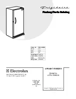
AFFU1766DW
Brand: Frigidaire Pages: 7

AFFU2066DW
Brand: Frigidaire Pages: 7

FFC0513D
Brand: Frigidaire Pages: 20

AFFU1466DW
Brand: Frigidaire Pages: 7
AFFU1466DW2
Brand: Frigidaire Pages: 2

Rex RND42353C
Brand: Electrolux Pages: 16

GT368
Brand: Electrolux Pages: 60

GT380
Brand: Electrolux Pages: 68

PRO 44133
Brand: Kenmore Pages: 13

28702
Brand: Kenmore Pages: 6

Viking 970
Brand: Kenmore Pages: 44

KLFC015MWD
Brand: Kenmore Pages: 22

FG-218W
Brand: Infiniton Pages: 74


