Cod: 0060300000-A
VENTILATION FAN
WARNING
READ AND SAVE THESE INSTRUCTIONS
Installer: Leave this manual with the homeowner.
CAUTION
CLEANING & MAINTENANCE
OPERATION
TO REDUCE THE RISK OF FIRE, ELECTRIC SHOCK, OR INJURY TO PERSONS, OBSERVE THE FOLLOWING:
1. Use this unit only in the manner intended by the manufacturer. If you have questions, contact the
manufacturer at the address or telephone number listed in the warranty.
2. Before servicing or cleaning the unit, switch power off at service panel and lock the service discon-
necting means to prevent power from being switched on accidentally. When the service disconnect-
ing means cannot be locked, securely fasten a prominent warning device, such as a tag, to the
service panel.
3. Installation work and electrical wiring must be done by a qualified person(s) in accordance with all
applicable codes and standards, including fire-rated construction codes and standards.
4. Sufficient air is needed for proper combustion and exhausting of gases through the flue (chimney)
of fuel burning equipment to prevent backdrafting. Follow the heating equipment manufacturer’s
guideline and safety standards such as those published by the National Fire Protection Association
(NFPA), and the American Society for Heating, Refrigeration and Air Conditioning Engineers
(ASHRAE), and the local code authorities.
5. When cutting or drilling into wall or ceiling, do not damage electrical wiring and other hidden utilities.
6. Ducted fans must always be vented to the outdoors.
7. Acceptable for use over a tub or shower when connected to a GFCI (Ground Fault Circuit Interrupt-
er) - protected branch circuit (ceiling installation only).
8. This unit must be grounded.
1. For general ventilating use only. Do not use to exhaust hazardous or explosive materials and vapors.
2. This product is designed for installation in ceilings up to a 12/12 pitch (45 degree angle). Duct connector must point up.
3. To avoid motor bearing damage and noisy and/or unbalanced impellers, keep drywall spray, construction dust, etc. off power unit.
4. Please read specification label on product for further information and requirements.
MODEL: PCD80XHP
See “Connect Wiring Diagram” for details.
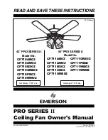
Time delay knob
Humidity sensor knob
T
H
OFF
30%
45%
60%
80%
60min
20min
40min
OFF
5min
The control box, located inside the fan housing, has two settings:
(1) The time delay knob sets the amount of time that the fan will continue to run at high speed
after switch is turned OFF, or the RH% limit is reached. It is adjustable from 5 to 60
minutes. Once the set time has elapsed, the fan will run at the Low speed. The time delay
setting is de-activated when set between OFF-5 mins (factory set to OFF). NOTE: for
humidity sensing applications, the fan will continue to run for 5 minutes after humidity is
below the RH% limit, even if the time delay knob is set between OFF-5 mins.
(2) The humidity sensor knob sets the RH% limit at which the fan will automatically operate at
high speed. The humidity sensor is de-activated when set between OFF-30% .
For quiet and efficient operation, long life, and attractive appearance - lower or remove grille and vacuum interior of unit with the dusting brush attach-
ment.
The motor is permanently lubricated and never needs oiling. If the motor bearings are making excessive or unusual noises, replace the motor with the
exact service motor. The impeller should also be replaced.
Operation Sequence
1. Turn power ON. The fan will run at low speed (40 CFM)and the humidity sensor will start sensing .
2. Turn switch ON. The fan will run at high speed(80 CFM) and will override the humidity sensor.
3. Turn switch OFF. The fan will continue to run at high speed until the time delay has elapsed (if enabled), and then will automatically change back
to low speed.
HUMIDITY SENSOR OPERATION
The fan runs continuously at a low speed and automatically boosts up to high speed when the relative humidity (RH%) in the room exceeds the RH%
limit set with the humidity sensor knob. If the fan continuously responds to changing environmental conditions (too sensitive), the RH% limit may need
to be adjusted.