background image

San Telequip (P) Ltd., 
504/505 Deron Heights, Baner Road, Baner 
Pune 411045, Mah, India 
Phone: +91-20-27293455,9764027070,8390069393          Connecting. Converting. Leading! 
email:

[email protected]


--------------------------------------------------------------------------------------------------------------------------------------- 

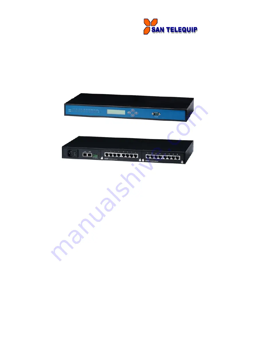
User’s Manual: SC10E16A1 Series 
Industrial Serial Device Server 


Content 

1


Introduction ............................................................................................. 6


1.1


Product Overview ..................................................................................................... 6


1.2


Features ..................................................................................................................... 6


2. Getting Started .......................................................................................... 6


2.1 Model Comparison ...................................................................................................... 6


2.3


Panel Layout and Dimensions ................................................................................ 7


LCM Configuration ........................................................................................ 9


1.1


Welcome Screen ....................................................................................................... 9


1.2


Main Menu Structure ................................................................................................ 9


1.2.1


Overview ......................................................................................................... 10


1.2.2


Network Settings ............................................................................................ 10


1.2.3


Serial Settings ................................................................................................ 11


Summary of Contents for SC10E16A1 Series

Page 1: ...info santelequip com 1 User s Manual SC10E16A1 Series Industrial Serial Device Server Content 1 Introduction 6 1 1 Product Overview 6 1 2 Features 6 2 Getting Started 6 2 1 Model Comparison 6 2 3 Panel Layout and Dimensions 7 LCM Configuration 9 1 1 Welcome Screen 9 1 2 Main Menu Structure 9 1 2 1 Overview 10 1 2 2 Network Settings 10 1 2 3 Serial Settings 11 ...

Page 2: ...tion 17 3 4 Serial 18 3 4 1 COM Configuration 19 3 4 2 COM Configuration Advanced Settings 20 3 5 Alert Settings 22 3 5 1 Email Settings 22 3 5 2 Alert Event 24 3 6 System Configuration 24 3 6 1 Link State 24 3 6 2 Log Settings 25 3 6 3 System Log 27 3 6 4 COM Log 27 3 6 5 Time Settings 28 3 6 6 Security Configuration 29 3 6 7 Import Export 30 3 6 8 Set to Default 30 3 6 9 Restart 30 4 CLI Configu...

Page 3: ...k Mode 42 4 4 4 Serial Settings 42 4 5 Alert Settings 43 4 5 1 Configuring E mail 43 4 5 2 Configuring Alert Event 44 4 6 System Configuration 44 4 6 1 Link State 44 4 6 2 Time Settings 45 4 6 3 Security Settings 46 4 7 Restoring Factory Default 46 4 8 Restart System 46 5 Link Modes and Applications 47 5 1 Link Mode Configuration 47 5 1 1 TCP Server Mode 47 5 1 2 TCP Client Mode 50 5 1 3 UDP Mode ...

Page 4: ...r Application Multiple TCP Connections 60 5 2 10TCP Server Application Multi Point TCP Pair Connections 61 6 VCOM Installation Troubleshooting 62 6 1 Enabling VCOM 62 6 1 1 VCOM driver setup 64 6 1 2 Limitations 64 6 1 3 Installation 64 6 1 4 Uninstalling 64 6 2 Enabling Virtual COM 64 6 2 1 Enable VCOM in Serial device servers 64 6 2 2 Running Serial IP in Windows 65 6 2 3 Configuring VCOM Ports ...

Page 5: ...il info santelequip com 5 7 3 Pin Assignments 80 7 3 1 Serial and RJ 45 Connectors 80 7 3 2 Serial and Female DB9 Connectors 81 7 3 3 Serial and Male DB9 Connectors 81 7 3 4 RJ 45 to Female DB9 Connection 82 7 3 5 RJ 45 to Male DB9 Connection 82 7 4 LED Indicators 83 7 5 Buzzer 84 8 Upgrade System Firmware 84 8 1 Upgrade Procedure 84 8 2 Error Messages 85 ...

Page 6: ...ling Modes Configuration Built in Web Server Serial Console Telnet Windows based Utility Monitor manage and control industrial field devices remotely 2 Getting Started 2 1 Model Comparison Model Description SC10E16A1 AC 16 Port Serial Device Servers RJ 45 AC 100 240V US plug SC10E16A1 DC 16 Port Serial Device Servers RJ 45 DC 24V 2 2 Inside the Package Inside the product purchased you will find th...

Page 7: ... adhere to all safety procedures described below SAN will not be held liable for any damages to property or personal injuries resulting from the installation or overall use of the device 1 Prepare the necessary cables power cord LAN cable serial cable etc do not connect the unit yet 2 Proceed then to plug the power source to the unit 3 Place the device in the desired location and connect it to the...

Page 8: ...n will be displayed in a graphical state It is also worth noting that as a first step to view your device s overall settings you should use Serial Manager the utility provided in the CD There will be however some buttons which will be present during almost each section 2 6 Factory Default Settings Upon arrival the device will be set as follows Parameters Default Values LAN 1 IP Address 10 0 50 100...

Page 9: ... below illustrates its buttons and corresponding functions 1 1 Welcome Screen When the device boots up the LCM will display LAN1 If you scroll down it will display LAN2 information The format is LAN1 Link down 10 0 50 100 1 2 Main Menu Structure Press the Menu Key to enter the main menu Press Scroll Down to go to the next layer or option Press Scroll Up to go to the back one layer or option Button...

Page 10: ...splay MAC address of LAN2 1 2 2Network Settings 1st layer 2nd layer 3rd layer 4th layer 5th layer Descriptions 2 Network set 1 Lan 1 1 IP config 1 Static IP Change to Static IP mode 2 DHCP Chang to DHCP mode 2 IP address Display Change LAN1 IP 3 Net mask Display Change Net mask 4 Gateway Display Change the Gateway IP 5 ARP Announce Time Setting in seconds 2 Lan 2 1 IP config 1 Static IP Change to ...

Page 11: ...yer 3rd layer 4th layer 5th layer Descriptions 3 Serial set 1 Select port Select a COM Port to configure 2 Parameter set 1 Baud Rate 1 50 Display Change baud rate 2 75 3 110 4 134 5 150 6 200 7 300 8 600 9 1200 10 2400 11 4800 12 9600 13 19200 14 38400 15 57600 16 115200 17 230400 18 460800 19 921600 2 Parity 1 None Display Change Parity 2 Odd 3 Even 4 Mark 5 Space 3 Data bits 1 5 bits Display Cha...

Page 12: ...nge UART delimiter to timer mode and set its time 2 Char Change UART delimiter to character mode and set the character 2 Serial to net 1 Disable Disable UART Delimiter 2 Enable 1 Timer Change UART delimiter to timer mode and set its time 2 Char Change UART delimiter to character mode and set the character 7 UART mode 1 232 Display Change UART mode to RS232 2 422 Display Change UART mode to RS422 3...

Page 13: ...erial ports 2 TCP client 1 Dest IP 1 Display Change Destination IP 1 2 Dest port 1 Display Change Destination port 1 3 Destination 2 1 Disable Disable destination 2 2 Enable Display Change Destination IP 2 and Destination port 2 4 Apply to all 1 No 2 Yes Apply Link mode Settings to all serial ports 3 UDP 1 Local port Display Change Local listening port 2 Dest IP1 Display Change Destination IP 1 3 ...

Page 14: ...console 1 Disable Disable Telnet console 2 Enable Enable Telnet console 2 Pwd protect 1 LCM console 1 No Disable LCM console password protection 2 Yes Enable and change the password 2 Reset button 1 No Disable the Reset button password protection 2 Yes Enable and change the password on Reset button 3 Ping 1 Lan 1 Use ping command to check specific IP address for LAN1 2 Lan 2 Use ping command to ch...

Page 15: ...016 Supported TABCTL32 OCX and mswinsck ocx files need to copy from CD or download from our Web site www santelequip com download Register the ocx into OS Open command prompt to type following commands regsvr32 c windows syswow64 TABCTL32 ocx regsvr32 c windows syswow64 mswinsck ocx Figure 3 To access the device s Web UI click on the Config by browser icon the web browser will open and prompt you ...

Page 16: ...page The information provided with networking settings The serial server is equipped with two LAN ports and provides two modes of settings 1 Dual Subnet Mode Subnet is a logically visible subdivision of an IP network The LAN 1 and LAN2 can be assigned to different subnets This feature gives the user flexible network manageability 2 Redundancy Mode A goal of redundant topologies is to eliminate net...

Page 17: ...gs accordingly Alternatively you may activate DHCP Dynamic Host Configuration Protocol client function by checking on Obtain an IP automatically field to obtain IP address gateway and subnet mask and DNS from a DHCP server automatically In addition You can fill in the time setting for ARP announce Figure 7 DNS Settings Fill in DNS Domain Name System information in order to have an external DNS ser...

Page 18: ...n Basic SNMP configurations such as Read Write Community SysName System Name SysLocation System Location and SysContact System Contact are supported In addition you can send SNMP Trap events to a SNMP Trap server by entering its IP address The changes will become effective immediately after a successful save Figure 9 3 4 Serial Click on the Serial link to open its submenu and COM1 settings Figure ...

Page 19: ...ivity protocols and their settings Figure are given in Link Modes and Applications Figure 10 Figure11 Match these settings with your serial device UART Mode Select between RS 232 RS 422 and RS 485 2 Wire or 4 Wire Baud Rate Select one of the baud rates from the dropdown box Parity Data Bits Stop Bits Configure them accordingly Flow Control Choose between No Flow Control RTS CTS Hardware Flow Contr...

Page 20: ... like to receive the Xon Xoff signals also enable Permit Xon Xoff Character Pass Through Enable Xon Xoff Special Control to allow synchronization between Xon Xoff states and DSR DTR signals Note Check Apply to all serial ports to execute these settings through all serial ports 3 4 2 COM Configuration Advanced Settings Click on the Advanced Settings button to open the dialog Figure 12 Figure 12 TCP...

Page 21: ... larger value If the bytes do not reach certain length condition the bytes could be discard to avoid devices connect on the TCP side running into issues To do this enable Discard Byte then select the condition you want and the length desired Attention Interval Timeout Manual Calculation The optimal Interval timeout depends on the application but it must be at least larger than one character interv...

Page 22: ...control is enabled it may deem necessary to disable the FIFO function to minimize the amount of data that is transmitted through the serial interface after a flow off event is triggered to reduce the possibility of overloading the buffer inside the serial device Please note that disabling this option on baud rates higher than 115200bps would reduce the data integrity noticeably Serial Buffer By de...

Page 23: ...thentication you need to enable SMTP server authentication required and fill in Username and Password Please contact your network administrator for Mail Server IP address and the Username and Password Note You can click on the Send test Mail button to verify your mail settings Figure 14 Figure 15 Attention It is also important to setup Default Gateway and DNS Servers in the Network Settings proper...

Page 24: ...ation Failure IP Change Password Change and Link Down SC10E16A1 Series supports three different types of event alerts which are E mail SNMP Trap and Relay Figure 16 3 6System Configuration Click on the System link to open its submenu and this will lead you to the Link State Figure 17 3 6 1 Link State Link State displays the information of each connection for all serial ports for debugging purposes...

Page 25: ...ne 411045 Mah India Phone 91 20 27293455 9764027070 8390069393 Connecting Converting Leading email info santelequip com 25 Figure 24 Figure 25 3 6 2 Log Settings The Syslog function is turned on by default and cannot be turned off It is used to log system events ...

Page 26: ...e cleared when the device restarts because they are stored in the RAM by default Log Level 3 We only allow logging at this level Enable Syslog Server enabling this option would allow you to send Syslog events to a remote Syslog server Syslog Server IP please specify the remote Syslog Serve IP Syslog Server Service Port please specify the remote Syslog Server Port Figure 27 COM Log Settings Log Dat...

Page 27: ...og server You can send COM logs to the same Syslog server used previously for logging events Syslog Server IP please specify the remote Syslog Server IP Syslog Server Service Port please specify the remote Syslog Server Port 3 6 3 System Log Display the current syslog stored in the device Figure 28 Click on Last Page to go to the last page Click on Show All Event to show all events in one page Cli...

Page 28: ...proceeding then to fill the IP address or hostname for it If a hostname is entered the DNS server must be configured properly a Time Zone can be selected as well Attention It is also important to setup Default Gateway and DNS Servers in the Network Settings properly so your SC10E16A1 Series can lookup DNS names and find the external NTP Server In case that you are located in a region where Dayligh...

Page 29: ...t is forgotten This will however erase all the data settings previously in the device so remember to always save it Figure 32 Security You can disable certain access methods to reduce the risk of system intrusion This includes the Web UI Telnet console LCM and the Reset Button Web Console Disable to prevent the Web UI from being accessed Telnet Console Disable to prevent the Telnet console from be...

Page 30: ... configuration click Export Configuration and a pop up dialog is prompted for saving the backup file on your computer It is important NOT to modify the saved configuration file by any editor Any modification to the file may corrupt the file it may not be used for restore To restore the configuration backup click Browse to locate the backup file and then click Import Configuration to upload the con...

Page 31: ...on find pin assignments in Section 6 3 2 The interface can be accessed with the following settings Baud rate 115200bps Parity None Data bits 8 bits Stop bit 1 bit Flow Control None 3 7 2 Telnet Console Please be aware that Windows Vista Windows 7 or higher do not have Telnet client installed by default to install Microsoft Telnet client on these systems 1 Click Start and then click Control Panel 2...

Page 32: ... command line interface console terminal and telnet to the device using its IP address The default username is admin and password is empty blank A main menu should appear Figure 36 Figure 37 Note 1 SC10E16A1 Series will automatically close the telnet connection after three minute of inactivity 2 Press the ESC key to return to the previous menu 3 Some changes to the device would take effect only af...

Page 33: ...s The table below illustrates its buttons and corresponding functions 1 3 Welcome Screen When the device boots up the LCM will display LAN1 If you scroll down it will display LAN2 information The format is LAN1 Link down 10 0 50 100 1 4 Main Menu Structure Press the Menu Key to enter the main menu Press Scroll Down to go to the next layer or option Press Scroll Up to go to the back one layer or op...

Page 34: ...C address of LAN2 1 4 6Network Settings 1st layer 2nd layer 3rd layer 4th layer 5th layer Descriptions 2 Network set 1 Lan 1 1 IP config 1 Static IP Change to Static IP mode 2 DHCP Chang to DHCP mode 2 IP address Display Change LAN1 IP 3 Net mask Display Change Net mask 4 Gateway Display Change the Gateway IP 5 ARP Announce Time Setting in seconds 2 Lan 2 1 IP config 1 Static IP Change to Static I...

Page 35: ... 1st layer 2nd layer 3rd layer 4th layer 5th layer Descriptions 3 Serial set 1 Select port Select a COM Port to configure 2 Parameter set 1 Baud Rate 1 50 Display Change baud rate 2 75 3 110 4 134 5 150 6 200 7 300 8 600 9 1200 10 2400 11 4800 12 9600 13 19200 14 38400 15 57600 16 115200 17 230400 18 460800 19 921600 2 Parity 1 None Display Change Parity 2 Odd 3 Even 4 Mark 5 Space ...

Page 36: ...are 6 Delimiter 1 Net to serial 1 Disable Disable UART Delimiter 2 Enable 1 Timer Change UART delimiter to timer mode and set its time 2 Char Change UART delimiter to character mode and set the character 2 Serial to net 1 Disable Disable UART Delimiter 2 Enable 1 Timer Change UART delimiter to timer mode and set its time 2 Char Change UART delimiter to character mode and set the character 7 UART m...

Page 37: ... the IP address 2 Enable 5 Apply to all 1 No 2 Yes Apply Link mode Settings to all serial ports 2 TCP client 1 Dest IP 1 Display Change Destination IP 1 2 Dest port 1 Display Change Destination port 1 3 Destinati on 2 1 Disable Disable destination 2 2 Enable Display Change Destination IP 2 and Destination port 2 4 Apply to all 1 No 2 Yes Apply Link mode Settings to all serial ports 3 UDP 1 Local p...

Page 38: ...2 Pwd protect 1 LCM console 1 No Disable LCM console password protection 2 Yes Enable and change the password 2 Reset button 1 No Disable the Reset button password protection 2 Yes Enable and change the password on Reset button 3 Ping 1 Lan 1 Use ping command to check specific IP address for LAN1 2 Lan 2 Use ping command to check specific IP address for LAN2 Restart 1st layer 2nd layer 3rd layer 4...

Page 39: ...ction allows you to change IP address subnet mask gateway and SNMP information Please note that the new settings will not take effect until the device is restarted Operation Main 2 Networking Figure 39 3 9 1 LAN1 LAN 2 Settings Enter LAN settings and you will see a menu to configure the DHCP IP address subnet mask and gateway of that LAN Operation Main 2 Networking 1 LAN 1 Settings Operation Main ...

Page 40: ...P Address manually Alternatively if you enable the DHCP option in LAN 1 Settings SC10E16A1 Series will retrieve the DNS server address from the DHCP server automatically Operation Main 2 Networking 3 DNS Settings Figure 01 SNMP Settings SC10E16A1 Series allows the user to Enable or Disable the SNMP function The changes will become effective immediately Basic SNMP configurations such as Read Write ...

Page 41: ...AN port Configure network settings of the bridge here Operation Main 2 Networking 6 Redundancy Settings Figure 43 3 10 COM Port Configuration SC10E16A1 Series allows you to configure the parameters of the COM port including COM Link mode and COM port parameters First enter the number of the COM port that you want to configure Figure 44 3 10 1 TCP Server for Link Mode TCP Server mode is the default...

Page 42: ...2 if enabled Operation Main 3 COM Port Setting 1 16 Select Port 1 Link Mode 2 TCP Client Figure 47 3 10 3 UDP Link Mode SC10E16A1 Series Link Mode can be configured to utilize UDP Note that UDP is a connection less protocol so data delivery is not guaranteed You will need to configure the settings of Destination IPs The Destination IP field supports input of IP range and up to eight Destination IP...

Page 43: ... Com Settings Figure 49 3 11 Alert Settings There are two sub menu settings included inside the Alert Settings which are E mail Settings and Alert Event Figure 50 3 11 1 Configuring E mail When an alert event triggered SC10E16A1 Series can send that event through email Here you can configure Sender s Email Address Receiver s Email Address up to 5 Mail Server and Require Authentication Operation Ma...

Page 44: ...d it should use to notify that event Email Trap or Relay Available events are Cold Start Warm Start Authentication Failure IP Address Change Password Change and Link Down Operation Main 4 Alert Settings 2 Alert Event Figure 52 3 12 System Configuration There are three sub menus included inside the System Settings which are Link State Time and Security Operation Main 5 System Figure 53 3 12 1 Link ...

Page 45: ...69393 Connecting Converting Leading email info santelequip com 45 Figure 54 3 12 2 Time Settings You can configure the system time manually or let SC10E16A1 Series retrieve time information from a NTP server The changed will take effect immediately after the settings are saved Operation Main 5 System 2 Time Figure 55 ...

Page 46: ... system intrusion Operation Main 5 System 3 Security Figure 56 Note Please be aware not to disable options 2 3 all together because further configuration would be not possible 3 13 Restoring Factory Default Choose and confirm this option to reset SC10E16A1 Series back to its default settings The device would restart automatically to apply the default settings Operation Main 8 Set to Default Figure...

Page 47: ...P Client can support Virtual COM application In the upcoming sections we will discuss how to setup different Link Modes properly Modes Supports TCP Server RAW VCOM Reverse Telnet Client VCOM UDP Connectionless protocol 4 1 1 TCP Server Mode SC10E16A1 Series can be configured as a TCP server in a TCP IP Network to listen for an incoming TCP client connection to a serial device After the connection ...

Page 48: ... defaults in TCP Server mode there are additional connection settings that can be configured By selecting the TCP Server mode a TCP Client program should be prepared to connect to SC10E16A1 Series Figure 60 For setting as a TCP Server please follow these steps Click on the COMX link under Serial on the left hand side Select TCP Server in the Link Modes TCP Server is the default link mode Also in t...

Page 49: ...ngs go to Sec 3 4 1 For Advanced settings go to Sec 3 4 2 Scroll to the bottom of the page and click on Save Configuration button to save the changes Other important variables to consider are IP Filter enables the Source IP option below to block an IP address from accessing the COM port Source IP specifies the device s Source IP which will be transmitting data to our Server In other words our Serv...

Page 50: ...Series can be configured as a TCP client in TCP IP Network to establish a connection with a TCP server in the host computer After the connection is established data can be transmitted between a serial device and a host computer in both directions this also applies to Virtual COM running in the client mode Figure 61 By selecting the TCP Client mode it means that a TCP Server program should be prepa...

Page 51: ...2 and Port 2 if necessary Two different servers can be set here for redundancy the second server has to be enabled by ticking the box Go to Response Behavior for more information on this setting For serial settings go to Sec 3 4 1 For Advanced settings go to Sec 3 4 2 Scroll to the bottom and click on Save Configuration button to save the changes 4 1 3 UDP Mode UDP is a faster but connectionless n...

Page 52: ...nation IPs of the remote UDP nodes Figure 63 SC10E16A1 Series also supports connectionless UDP protocol compared to the connection oriented TCP protocol Please be aware that even though UDP provides better efficiency in terms of response time and resource usage it does not guarantee data delivery It is recommended to utilize UDP only with cyclic polling protocols where each request is repeated and...

Page 53: ... traffic load We have tested that SC10E16A1 Series can handle up to 100 UDP nodes baud rate 9600 bps request interval 100ms and data length 30bytes Enter the Local Listening Port This is the port that SC10E16A1 Series should listen to Match this setting in the UDP program usually called destination port in the UDP program For serial settings go to Sec 3 4 1 For Advanced settings go to Sec 3 4 2 Sc...

Page 54: ...C10E16A1 Series in TCP Server mode properly Click on the dropdown box of the Mode option and switch to Virtual COM to enabled Virtual COM application in SC10E16A1 Series Scroll to the bottom of the page and click on Save Configuration button to save the changes Configure Virtual COM in the Operating System For Windows refer to Chapter 5 For Linux refer to a separate manual included in the Linux dr...

Page 55: ...in the Client mode if SC10E16A1 Series uses dynamic IP DHCP because setting a static IP address in Virtual COM s Control Panel in the Operating System is not possible Figure 66 Follow Sec 4 1 2 to configure SC10E16A1 Series in TCP Client mode properly Click on the dropdown box of the Mode option and switch to Virtual COM to enabled Virtual COM application in SC10E16A1 Series Scroll to the bottom o...

Page 56: ... ports would not be used 4 2 5 TCP Server Application Configure SC10E16A1 Series as a Pair Connection Master Pair Connection is useful when pairing up two serial devices over the Ethernet or when it is impossible to install Virtual COM in the serial device Pair connection does require two SC10E16A1 Series to work in pair one would be the Pair Connection Master and the other would be the Pair Conne...

Page 57: ... Connection Slave is shown in Figure it is necessary to pair up with a Pair Connection Master Please setup a Pair Connection Master first before proceeding Figure 68 Follow Sec 4 1 2 to configure SC10E16A1 Series in TCP Client mode properly Click on the dropdown box of the Mode option and switch to Virtual COM to enabled Virtual COM application in SC10E16A1 Series Match the Destination IP with the...

Page 58: ... 69 Follow Sec 4 2 1to configure SC10E16A1 Series in TCP Server mode properly Click on the dropdown box of the Mode option and switch to Reverse Telnet to enabled Reverse Telnet application in SC10E16A1 Series Scroll to the bottom of the page and click on Save Configuration button to save the changes 4 2 8 UDP Application Multi Point Pair Connection It is also possible to setup pair connection in ...

Page 59: ...on IP Destination Port SC10E16A1 Series Master COM1 10 0 50 100 UDP 5000 10 0 50 200 10 0 50 202 5000 SC10E16A1 Series Master COM1 10 0 50 100 UDP 5001 10 0 50 200 10 0 50 201 5000 SC10E16A1 Series Master COM1 10 0 50 100 UDP 5002 10 0 50 200 5000 SC10E16A1 Series Slave 1 COM1 10 0 50 200 UDP 5000 10 0 50 100 5000 SC10E16A1 Series Slave 1 COM2 10 0 50 200 UDP 5001 10 0 50 100 5001 SC10E16A1 Series...

Page 60: ...nnection option will allow up to a maximum of four TCP Client connections Note that it is also possible to use this multi connection feature in conjunction with other TCP Server applications such as Virtual COM Pair Connection and Reverse Telnet For example enabling multi connection along with Pair Connection will result in Multi Point Pair Connection in TCP mode Sec 4 2 10 For more information on...

Page 61: ...ol pins with RS 232 or RS 485 it is possible to setup pair connection in UDP mode Sec 4 2 8 After multi connection is enabled in the WebUI refer to the following table to setup Pair Connection as in Figure IP Address Link Mode Application Local Listening Port Destination IP Destination Port SC10E16A1 Series Master COM1 10 0 50 100 TCP Server Pair Connection Master 4660 SC10E16A1 Series Slave 1 COM...

Page 62: ...santelequip com 62 5 VCOM Installation Troubleshooting 5 1 Enabling VCOM SC10E16A1 Series will encapsulate control packets on top of the real data when Virtual COM is enabled This will allow the Virtual COM port in the Windows Linux system to access SC10E16A1 Series COM ports Remember that VCOM can only be enabled on TCP Server Mode or TCP Client Figure Figure 73 ...

Page 63: ...93455 9764027070 8390069393 Connecting Converting Leading email info santelequip com 63 Figure 74 Virtual COM allows remote access of serial devices over TCP IP networks through Serial IP Virtual COM ports that work like local native COM ports Figure is a Virtual COM connection diagram Figure 75 ...

Page 64: ...o COM4096 is allowed Note that COM ports already occupied by the system or other devices will not be available 5 1 3 Installation Run the Virtual COM setup file included in the CD or download a copy from our website to install the Virtual COM driver for the operating system Turn off your anti virus software and try again if installation fails At the end of the installation please select at least o...

Page 65: ... Windows Find Serial IP Control Panel from Start All Programs Serial IP Control Panel In the Windows Control Panel open the Serial IP applet In the Windows notification area Figure right click in the Serial IP tray icon and click on Configure to open the Control Panel Figure 77 If no Virtual COM port is selected a dialog will pop up and asks to select at least one port as the Virtual COM port befo...

Page 66: ...hts Baner Road Baner Pune 411045 Mah India Phone 91 20 27293455 9764027070 8390069393 Connecting Converting Leading email info santelequip com 66 Figure 78 After at least one Virtual COM port is selected the Control Panel will show Figure ...

Page 67: ...add or remove Virtual COM ports from the list The right hand side of the Control Panel shows the configurations of the selected Virtual COM port marked in blue Each Virtual COM port can have its own settings Note The changes to Virtual COM ports apply immediately so there is no need to save the settings manually However if the Virtual COM port is already in use it is necessary to close the Virtual...

Page 68: ...d enter the IP Address of the serial device server with the Port Number specified The Port Number here is the Local Listening Port for the serial device server If the serial device server is running in TCP Client mode Serial IP should be the TCP Server waiting for a serial device server to connect it Enable Accept Connections and enter the Port Number The Port Number here is the Destination Port o...

Page 69: ...etwork connections To test the Virtual COM connection click the Configuration Wizard button and then click Start button in the pop up window Figure If the test passes all checks should be in green To apply the changes in the Configuration Wizard window to the Control Panel click on Use Settings Click on Copy to copy the results to the system clipboard To transfer the settings between Virtual COM p...

Page 70: ...one 91 20 27293455 9764027070 8390069393 Connecting Converting Leading email info santelequip com 70 5 2 4 Exceptions Figure 82 If the exclamation mark begins with Warning timeout trying x x x x as in Figure recheck the VCOM IP and Port configuration or the PC s network configuration ...

Page 71: ...dia Phone 91 20 27293455 9764027070 8390069393 Connecting Converting Leading email info santelequip com 71 Figure 83 If there is a check with Raw Connection Detected and an exclamation mark with Client not licensed for this server Figure enable VCOM in the serial device server ...

Page 72: ...ing Leading email info santelequip com 72 Figure 84 If there is a check with Telnet Protocol Detected and an exclamation mark with Client not licensed for this server as in Figure this means that there is a licensing issue between the serial device server and Serial IP Please contact SAN technical support to obtain the correct VCOM software ...

Page 73: ...93455 9764027070 8390069393 Connecting Converting Leading email info santelequip com 73 Figure 85 If the exclamation mark begins with Server requires username password login Figure It means VCOM Authentication in the serial device server is enabled but credentials in the Serial IP are not enabled ...

Page 74: ...e 91 20 27293455 9764027070 8390069393 Connecting Converting Leading email info santelequip com 74 Figure 86 If the exclamation mark begins with a Username and or password incorrect Figure this means the wrong username and or password were entered and the authentication process failed ...

Page 75: ...55 9764027070 8390069393 Connecting Converting Leading email info santelequip com 75 Figure 87 If the exclamation mark begins with No login password prompts received from server Figure it means credentials in the Serial IP is enabled but VCOM Authentication in the serial device server is not enabled ...

Page 76: ...con in the Windows notification area In the Windows notification area right click in the Serial IP tray icon and click on Port Monitor to open the Port Monitor Click on the Port Monitor button in the Serial IP Control Panel 5 3 2 The Activity Panel Figure 88 The Activity panel provides a real time display of the status of all Serial IP COM ports Figure If the Virtual COM Port is open and is proper...

Page 77: ... Serial IP COM ports operations Figure Click on Enable Trace to start logging Virtual COM communication Click on File Save As and send the log to SAN for analysis if problems arise with Virtual COM 5 3 4 Serial IP Advanced Settings In the Serial IP Control Panel Click on the Advanced button to open Advanced Settings window Figure Click on Use Default Settings to load the default settings Figure 90...

Page 78: ...pt Server Connection If credential is set to Windows Credentials VCOM automatically adds the current Windows domain to the username COM Port Control Keep Alive Controls the interval at which VCOM will issue the keep alive message if no there is no activity Maximum Connection Recovery Interval Controls the maximum time for Restore Failed Connection Enable SETXON SETXOFF COM Port Commands This optio...

Page 79: ...ware selectable Ports 8 16 Ports Baud Rate 300 921600Kbps Parity None Odd Even Space Mark Data Bits 5 6 7 8 Stop Bits 1 2 Flow Control None Xon Xoff RTS CTS Power Characteristics Input Voltage 100 240VAC Input Current 100VAC 0 09A Power Consumption Approx 8 5W max Power Redundancy No Reverse Polarity Protection Yes Connector AC Inlet Mechanicals Dimensions 436 mm x 43 5 mm x 200 mm Installation Ra...

Page 80: ...Syslog TCP Telnet UDP Configuration Serial Manager Web UI Serial console Telnet Virtual COM Windows Linux redirection software Link Modes TCP Server 4 connections Virtual COM or Reverse Telnet TCP Client Dual destinations or Virtual COM UDP Up to 8 ranges of IPs 6 3 Pin Assignments 6 3 1 Serial and RJ 45 Connectors Ethernet RS 232 RS 422 RS 485 Pin 1 Tx RTS Pin 2 Tx DTR TX Pin 3 Rx TXD TX Pin 4 SG...

Page 81: ... info santelequip com 81 6 3 2 Serial and Female DB9 Connectors RS 232 RS 485 RS 422 Pin 1 Pin 2 RXD Data RX Pin 3 TXD TX Pin 4 DTR TX Pin 5 SG SG SG Pin 6 DSR Data RX Pin 7 RTS Pin 8 CTS Pin 9 6 3 3 Serial and Male DB9 Connectors RS 232 RS 485 RS 422 Pin 1 Pin 2 RXD Data RX Pin 3 TXD TX Pin 4 DTR TX Pin 5 SG SG SG Pin 6 DSR Data RX Pin 7 RTS Pin 8 CTS Pin 9 ...

Page 82: ...male DB9 Connection RJ45 Cross Over Female DB9 RTS Pin 1 Pin 8 CTS DTR Pin 2 Pin 6 DSR TXD Pin 3 Pin 2 RXD SG Pin 4 Pin 5 GND SG Pin 5 RXD Pin 6 Pin 3 TXD DSR Pin 7 Pin 4 DTR CTS Pin 8 Pin 7 RTS 6 3 5 RJ 45 to Male DB9 Connection RJ45 Straight Through Male DB9 RTS Pin 1 Pin7 RTS DTR Pin 2 Pin4 DTR TXD Pin 3 Pin3 TXD SG Pin 4 Pin 5 SG SG Pin 5 RXD Pin 6 Pin2 RXD DSR Pin 7 Pin6 DSR CTS Pin 8 Pin 8 C...

Page 83: ...3 TXD 6 4 DTR 7 5 GND 4 5 6 DSR 2 7 RTS 8 8 CTS 1 9 RI 6 4 LED Indicators Name Color Status Message Power Green On Power is connected Off Power is not connected Ready Green On Booting up Blinking In Activity COM Tx Rx Green Blinking SerialPort Transmission Off No Data Transmission LAN Orange On Ethernet is connected at 100Mbps Green Off Ethernet is Disconnected Blinking Data is transmitting on Eth...

Page 84: ...e sure the PC and the SC10E16A1 Series are on the same network use the ping command or Serial Manager utility for it Edit dll bat to fit the system requirements be sure to save your settings before Run linux_dl for example linux_dl_v2_zImage bin 10 0 50 100 SC10E16A1 Series will automatically restart each time after the firmware is successfully downloaded The upgrade process should take around one...

Page 85: ...y not be successful if errors occurred during the process Error Cause Message Illegal Hex file format Hex File Text Error Hex File Check Sum Error Hex File Format Error Hex File End of Record Error Handshaking problem SC10E16A1 Series ACK Start Address Error SC10E16A1 Series ACK length Error SC10E16A1 Series ACK Response Command Error Configuration file Remote IP not found Open configuration file ...

Reviews: