Samsung SpinPoint M9T, Product Manual
The Samsung SpinPoint M9T is a premium internal hard drive that offers ample storage capacity for your digital files. With a user-friendly interface, accessing its full potential is made easy with the easy-to-follow Product Manual. You can download the manual for free at manualshive.com, ensuring a seamless installation and optimal performance.
Share
Download


Reviews:
No comments
Related manuals for SpinPoint M9T

CS100
Brand: Canon Pages: 11
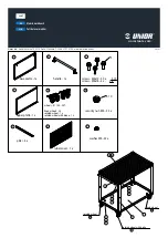
940T
Brand: Unior Pages: 2

Biggest S2S
Brand: LaCie Pages: 2

Vertical Modular Paint Storage
Brand: Blueshark Studio Pages: 7

FMT1203
Brand: Fast Mover Pages: 2

URBAN 100.1P DEC
Brand: garofalo Pages: 16

Travan
Brand: Quantum Pages: 32

HandyDrive-5
Brand: Fujitsu Pages: 17

LTO-5
Brand: Fujitsu Pages: 34

MAS3367FC
Brand: Fujitsu Pages: 114

MAU3036NC
Brand: Fujitsu Pages: 130

GRANPOWER500 TEAMSERVER Series
Brand: Fujitsu Pages: 14

MAA3182
Brand: Fujitsu Pages: 142

MAN3367FC - Enterprise 36.7 GB Hard Drive
Brand: Fujitsu Pages: 148

HARD DISK DRIVES MAW3073FC
Brand: Fujitsu Pages: 112

LTO-6
Brand: Fujitsu Pages: 52

IRF-1D series
Brand: Fujitsu Pages: 182

MAP3147FC
Brand: Fujitsu Pages: 114


