background image

SF4300C

INKJET PRINTER COMPOUND 

CONTENTS

1. Precaution

2. Referential Information

3. Specifications

4. Disassembly & Assembly

5. Circuit

6. Repair

7. Exploded View

8. Packing

9. Circuit Diagram & Parts List

10. Block Diagram

11. PCB Layout

12. Wiring Diagram

SERVICE

Manual
Summary of Contents for SF-4300C

Page 1: ...OUND CONTENTS 1 Precaution 2 Referential Information 3 Specifications 4 Disassembly Assembly 5 Circuit 6 Repair 7 Exploded View 8 Packing 9 Circuit Diagram Parts List 10 Block Diagram 11 PCB Layout 12 Wiring Diagram SERVICEManual ...

Page 2: ...ELECTRONICS ...

Page 3: ...fall causing serious dam age to the product 3 Use this product in a well ventilated place 4 Slots are provided for ventilation Never push objects of any kind into this product through these slots as they may result in a fire or electric shock Never spill liquid of any kind on the prod uct 5 Power supply cords should be routed so that they are not likely to be walked 6 Use this product in a place b...

Page 4: ...ded soldering iron 5 Use static electricity protective solder Solder not marked Ôstatic electricity protectiveÕ may accu mulate static electricity that damages ESD parts 6 Do not get rid of the static electricity protective cover of ESD parts until you are ready to replace them Most of ESD parts are packed with elec tricity conducting materials in contact with ESD parts leads 7 Make static electri...

Page 5: ... INTERFACE UART Universal Asynchronous Receiver Transmitter ECP Expended Capasilities port 8bits Data CR Carriage Return LF LINE FEED CIP COLOR IMAGE PROCESSOR CCD Charge Coupled Device A D ANALOG TO DIGITAL D A DIGITAL TO ANALOG LIU Line Interface Unit TIT Transformer Input from Transformer ROT Receive Output Transformer LI Line Input ...

Page 6: ...B4 B5 B6 B7 B8 CERAMIC CASE 732 03 DIR A1 A2 A3 A4 A5 A6 A7 A8 GND LOGIC AND CONNECTION DIAGRAMS DIP TOP VIEW J SUFFIX PLASTIC CASE 738 03 N SUFFIX SOIC CASE 751D 03 DW SUFFIX 20 1 20 1 20 1 1 Gate 2 Drain 3 Source 1 2 3 C E B R1 R2 R1 10KΩ R2 0 6KΩ TO 220 1 Base 2 Emitter 3 Collector 1 3 2 SOT 23 1 Base 2 Collector 3 Emitter 1 2 3 SOT 89 ...

Page 7: ...Samsung Electronics 2 3 8 DIP 8 SOP BLOCK DIAGRAM 1 2 3 4 8 7 OUT 1 IN1 _ _ IN1 GND Vcc OUT 2 IN2 IN2 6 5 Vcc Q6 Q6 Q12 Q17 Q19 Q20 R1 Q15 Q18 Q11 C1 Q10 Q9 Q4 Q3 Q2 Q1 Q8 Q13 Q14 Q21 R2 OUT IN IN ...

Page 8: ...8 7 2 _ 1 _ 2 50k This device contains 45 active transistors Rf Rj Optional Differential Gian 2 x 50k 125k FC2 1 Vcc Vo1 Vo2 Speaker CD GND Bias Circuit MC34119 Chip Disable 8 1 8 8 1 1 P SUFFIX PLASTIC PACKAGE CASE 626 D SUFFIX PLASTIC PACKAGE CASE 751 SO 8 DTB SUFFIX PLASTIC PACKAGE CASE 948J TSSOP 14DIP BLOCK DIAGRAM 14SOP 1 1 OUT2 OUT1 Vcc IN1 IN2 IN1 _ _ _ _ IN2 1 2 3 4 5 6 7 14 13 12 11 10 9...

Page 9: ... 31 32 30 26 25 24 23 29 28 27 PIN CONFIGURATION Top Views KM416C V10 2 00BJ KM416C V10 2 00BT 1 Emitter 2 Base 3 Collector 1 2 3 TO 92 A15 A14 A13 A12 A11 A10 A9 A8 NC NC NC NC NC A17 A7 A6 A5 A4 A3 A2 A1 RY BY WE RESET A16 BYTE Vss DQ15 A 1 DQ7 DQ14 DQ6 DQ13 DQ5 DQ12 DQ11 DQ3 DQ2 DQ9 DQ1 DQ8 DQ0 OE Vss CE A0 DQ10 DQ4 Vcc 1 2 3 4 5 6 7 8 9 10 13 14 16 17 18 19 20 21 22 23 24 15 11 12 48 47 46 45 ...

Page 10: ... 15 14 13 12 11 10 9 8 7 6 5 4 3 2 1 TEA3718SP Multiwatt 15 TEA3718SFP SO 20 TEA3718DP TEA3718SDP Powerdip 12 2 2 Us OUT B Us Us Uss PHASE IN1 N C N C GND GND PULSE TIME SENSE REFERENCE IN0 COMPARATOR INPUT N C PRE ALARM OUT GND GND OUT A Us N C GND ALARM OUTPUT REFERENCE IN0 IN1 Uss Note HEATSINK SURFACE CONNECTED TO PIN B PHASE COMPARATOR INPUT DUT B SENSE PULSE TIME DUT A 3 1 8 10 9 4 7 5 6 2 1...

Page 11: ...DACK NC NC NC NC NC NC EEDATA EECLK GND9 GOP3 TONE GOP4 nRSTO GOP8 nIORD2 GOP9 CLKOUT GOP10 FIREPULSE GOP11 GOP6 nIOWR2 GOP7 nIORD1 VCC8 NC NC NC KS32C6200 160 TQFP Top View KS16116 7 1 2 3 4 5 6 7 8 9 10 11 12 13 14 15 16 17 18 19 20 D11 D10 D9 D8 VSS D7 D6 D5 D4 VDD D3 D2 D1 D0 VSS ADDR4 ADDR3 ADDR2 ADDR1 ADDR0 60 59 58 57 56 55 54 53 52 51 50 49 48 47 46 45 44 43 42 41 VDD GPO0 GPO1 GPO2 GPO3 V...

Page 12: ...ause a short circuit between close pins 7 Locate parts in place It has a great influence on soldering 8 Do not use repaired parts again 9 Check the soldered part 10 Defective variable resistors are not adjustable Be sure to replace them 11 After finishing the job check if there are cold sol dered parts 2 2 2 Tools to Replace Chips The following tools are used to replace chip parts iron with thin t...

Page 13: ...ving wire 2 Use two irons a Use an iron with small flat tip b Apply heat to both ends of the part at the same time c Remove the part with the tip of the iron while melting d Remove the remaining solder completely with solder removing wire 2 2 4 c Installation 1 Clean the place where new parts will be installed 2 Apply water soluble flux 3 Locate a part exactly in place Be careful not to shift it 4...

Page 14: ...a Choose an iron tip that suits the shape and the size of IC b Use ÔthinÕ tip to contact legs of IC c Put the tip right in front of the legs of IC d Twist the iron carefully when solder melts e Raise and remove IC 2 Use a ventilation device a Choose an injector that suits IC b Choose the temperature and the ventilation speed normal temperature 7 speed 4 c Use IC removing tools d Preheat it for abo...

Page 15: ...dressable Mono 600 5 600DPI 120051200 DPI addressable Printing Width 8 Inch Feeding Automatic 100 sheets for normal cut sheets coating paper Method Manual Recommended for thick media fashion paper envolope postcard Banner paper Emulation Host Based Printing GDI Printer Driver Window 3 1 3 11 and Windows 95 drivers Interface IEEE 1284 Compatible Parallel Interface ECP Mono Ink Color Ink Print Head ...

Page 16: ...WAIN Compatible Yes Pre Scan Using Carrier Sheet Speed Color about 1 PPM Mono about 2 PPM Resolution Color 300 X 300 DPI for SmartJet C only Mono 300 X 300 DPI Gray Scale 256 Level Printing Width 8 lnch Feeding Manual Yes Interface IEEE 1284 Compatible Parallel Interface ECP ...

Page 17: ...ridge FF STOP START COPY LEDs on OPE 3EA Ready Busy Scan Fax Real Time Clock None Fax Monitoring Speaker Yes Ring Volume Control Switch None Paper Tray BIN Type up to 100 sheets Modem Speed Max 9600 bps Coding Method MH MR MMR Error Correction Mode LCD None Answering Machine I F None Extension Phone I F 1 Jack Extension Phone Transfer PC Interface IEEE 1284 Parallel Interface ECP Fax Send Resoluti...

Page 18: ...hain Dial No No On Hook Dial No No Last Number Redial No No Telephone Auto Busy Redial No No No Power Operation No No Hold Mute No No Pause No Yes Ring Volume Control No No Flash No No Tone Pulse Switch No Yes Sensors No paper sensor Paper jam sensor Error Indicator Yes On LED Yes On PC Screen Voice Request No No Others TTI Yes Rx Terminal ID No No Polling No No DRPD U S A Yes Other countries No M...

Page 19: ... Gray Scale No Yes Reduction Copy No Yes Enlargement Copy No No 4 Electrical Environment Power Source AC 220 240V 0 3A 50 60Hz Dimension W5D5H 422 mm 5 237 mm 5 180 mm Weight 3 7kg 5 Accessories Tel Handset No Curl Cord No Tel Line Yes Power Cord Yes Software 1 CD ROM Manual Printer Driver PC Fax Manual 1EA Ink Mono Ink Yes Cartridge Color Ink Yes Xerox s OCR S W and scanner editor are recommended...

Page 20: ...ont Cover 1 Fig 4 1 Taking Off Front Cover 2 Disconnect power cords and printer cable from the printer Unscrew 1 screws on rear cover to separate ink cartridge storage Push Guide Extension in the direction of the arrow symbol Remove 2 screws between front cover and bot tom cover Hold the upper part of front cover with both hands and lift the front cover holding down rear cover Separate front cover...

Page 21: ...upper part of rear cover Unhook right and the left hooks of bottom cover by pushing them in Separate rear cover in the same direction that the automatic sheet feeder is mounted Fig 4 3 Separating Automatic Sheet Feeder Remove various wires fixed on the side of automatic sheet feeder Unscrew 2 screws on automatic sheet feeder Push slightly and disconnect the hook ÒAÓ fixed to the main frame Separat...

Page 22: ...board Unscrew 3 screws fixed to the main board and separate the main board in the direction of the arrow symbol Fig 4 4 Separating Main Circuit Board 4 5 Separating Power Circuit Board Fig 4 5 Separating Power Circuit Board Unscrew 2 screws that fix the right and left ground wire Press the hook ÒAÓ on the middle of the housing and separate power circuit board ...

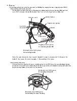
Page 23: ...age Push outside right and left hooks on the side of the engine unhook them and separate the engine in the direction of the arrow symbol 4 7 Separating Home Assembly Fig 4 7 Separating Home Assembly Unscrew 1 screw fixed to the back of the engine and separate home assembly from the engine Pull out the wiper and the cap in the direction of the arrow symbol to separate them ...

Page 24: ...ulley in and separate the right part of the timing belt from motor pulley Pull out carrier shaft and separate carrier Assembly Holder Cable 4 9 Separating Frame Base Assembly Fig 4 9 Separating Frame Base Assembly Refer to 4 8 to separate carrier Assembly first Separate 4 roller friction Assembly on the back of the engine and then actuator feed Separate frame base Assembly by lifting the back Fram...

Page 25: ...t from the engine Turn the bearing feed R in the direction of the arrow symbol to separate it from the main frame Push feed roller on the right to separate it from the main frame Bearing Feed R 4 11 Separating Bracket Line Feed Assembly Fig 4 11 Separating Bracket Line Feed Assembly Refer to 4 10 to separate feed roller Assembly Unscrew 2 screws and separate bracket line feed Assembly Bracket Line...

Page 26: ...rame ASF Separate the cam pickup on the right and then unscrew the right screw to separate the finger part Pull out the clutch and then unscrew 1 left screw to separate the clutch part Separate the guide finger from shaft pickup Push shaft pickup to the right to separate Bend plate knockup slightly and then separate it from the frame ASF ...

Page 27: ...ng LIU board Fig 4 13 Separating LIU board Refer to 4 12 to separate automatic sheet feeder from the engine Separate the connector Unscrew 2 screws fixed to LIU board Separate LIU board from the engine in the direction of the arrow symbol ...

Page 28: ...h up scan Assembly in the direction of the arrow symbol to separate it from the carriage 4 15 Separating White Reference Sheet Fig 4 15 Separating White Reference Sheet Remove contaminated white reference sheet completely from the frame base Ask for new white reference sheet White Reference Sheet Frame Base ...

Page 29: ...al LIU TXD MCLK 30MHz POR ROMCS RD WR D0 D15 D0 D15 D0 D7 A0 A17 A0 A9 A0 A4 RST OUT PD0 PD7 P ERROR P PE P BUSY P ACK P SLCT P INIT P STB 245DIR P SLCTIN P AUTOFD MCS MIRQ RD WR RASO 1 WR UCAS LCAS F POR LIU RXD IP CLK XDACK XDREQ IP CS RD WR D0 D15 A0 A4 LFPHA MFP CONTROLLER KS32C6200 LFPHB LFIA0 LFIA1 LFIB0 LFIB1 CR REF CRPHA CRPHB CRIA0 CRIA1 CRIB0 CRIB1 HEAD EN HEAD DATA HGA1 HGA13 HOE1 HOE16...

Page 30: ...om the outside is used with out being divided inside 5 1 2 2 DATA ADDRESS BUS CONTROL RD WR RD WR signals are synchronized with MCLK 30MHz and become LOW ACTIVE These signals are strobe signals used to read and write data when each CHIP SELECT is connected with RD and WR pin of RAM ROM MODEM and the outside devices and becomes active CHIP SELECT CSO ROMCS MCS IP CS CIP1A U17 CHIP SELECT LOW ACTIVE...

Page 31: ...hannel 0 RXD0 TXD0 is used here and the baud rate is 9600bps 5 1 2 3 LIU Line Interface Unit SERIAL COMMUNICATION PART TxD TxD RxD IRS RE IR Tx Encoder IR Rx Decoder 0 0 1 1 RxD UART Block Fig 5 1 2 UART BLOCK DIAGRAM TXD START D0 D1 D2 D3 D4 D5 D6 D7 STOP RXD START D0 D1 D2 D3 D4 D5 D6 D7 STOP Fig 5 1 3 UART DATA FORMAT START STOP 1BIT EACH BAUD RATE 9600bps CPU I F SUPPORTS BOTH INTERRUPT POLLIN...

Page 32: ...OWLEDGE signal and drives DMAchannel 0 to produce CHIP SELECT and READ STROBE RD at the external device and bring data from it It generates address of destination memory CHIP SELECT and WRITE STROBE WR in order to move this data into destination memory and then stores the data 5 1 2 4 External DMA MCLK XDREQ XDACK D 15 0 RD WR Fig 5 1 4 EXTERNAL DMA TIMING DIAGRAM ...

Page 33: ...rt connected with the computer through the centronics connector makes possible parallel interface with the computer Data is transmitted according to the standard of IEEE P1284 This MFP controller supports compatibility mode the traditional way to transmit print data nibble mode 4bit data to upload data to the computer and duplex high speed transmission with the computer ECP Extended Capabilities P...

Page 34: ...OBE BUSY PPD 7 0 nAUTOFD BYTE0 DATA BYTE COMMAND BYTE BYTE1 Fig 5 1 6 ECP Hardware Handshaking Timing forward nACK nAUTOFD PPD 7 0 BUSY nINIT PE BYTE0 DATA BYTE COMMAND BYTE BYTE1 Fig 5 1 7 ECP Hardware Handshaking Timing reverse ...

Page 35: ...e head OK 2PRINT and HEAD DATA It has double height print head system 208 nozzles for mono and 192 nozzles for color and uses PHGA 13 1 PHOE 16 1 signals and HEAD EN to drive these nozzles Fig 5 1 8 is timing diagram of each signal 5 1 2 7 INKJET HEAD CONTROLLER PHGA Signal PHOE Signal Fire Enable Timer Pre Heat Pulse Width Front End Delay Back End Delay Pr Heat Delay Width Fire Pulse Width tp PD ...

Page 36: ...0 1 LFPHA LFPHB LFIA0 1 LFIB0 1 MFP Controller KS32C6200 U15 supports 2 stepper motors It controls CR Carriage Return motor used to read and print documents and LF Line Feed motor used to feed and eject paper CR motor controller can support 75 150 200 300 600 or 1200dpi according to resolution while LF motor controller supports uni polar and bi polar according to the kind of motors Though full ste...

Page 37: ...ET OUT IS ACTIVE IOWR 1 GOP 5 FAULT TEST 0 H DEFAULT STATE L CHECK FAULT IN PRINTHEAD IOWR 2 GOP 6 RX CTL 0 H MODEM RX PATH CONNECTION L REMOTE START DETECTION PATH CONNECTION IORD 1 GOP 7 HEAD EN 0 H PRINTHEAD IS DISABLE L PRINTHEAD IS ENABLE IORD 2 GOP 8 TONE CTL 0 H MONITORING TX RX SOUND L BEEP SOUND CLKOUT GOP 9 IP CLK 0 CIP CLOCK FIREPS GOP 10 RST OUT 0 H EXT CHIP IS ACTIVE L EXT CHIP IS RES...

Page 38: ...INT 2 GIP 3 OK2PRINT I H NO FAULT IN PRINTHEAD L FAULT IN PRINTHEAD EDREQ GIP 4 XDREQ I H NO DMA REQUEST FROM CIP L DMA REQUEST FROM CIP UCLK GIP 5 HEAD DATA I CODE DATA FROM PRINTHEAD TCK GIOP 0 TCK I O TEST PIN FOR EMULATOR CLOCK TMS GIOP 1 TMS I O TEST PIN FOR EMULATOR DATA MODE TDI GIOP 2 TDI I O TEST PIN FOR EMULATOR DATA FROM EMULATOR TRST GIOP 3 TRST I O TEST PIN FOR EMULATOR RESET TO TAP C...

Page 39: ...e whole system by initializing MFP controller KS32C6200 after primary reset Primary reset makes flash memory wait in READ mode to fetch program codes and sec ondary reset makes the main controller KS53C6200 wake up and initialize external peripherals to operate the system Fig 5 1 10 is Power Reset Timing Diagram 5 1 2 10 RESET CIRCUIT supply Voltage F POR POR PnRST Internal Reset 256 MCLK Reset fi...

Page 40: ...nning RESET LOW ACTIVE Flash memory and KS32C6200 are reset first Thereafter modem print control parts and CIP Color Image Processor linked to RST OUT terminal of KS32C6200 are reset as well KIA7045F output terminal of open drain structure is pulled up 5 1k and put out 5 1 3 SYSTEM MEMORY System memory consists of 512KB flash memory and 2MB DRAM Flash memory and DRAM are selected by each CHIP SELE...

Page 41: ...cuits 5 1 4 2 CIP1A U17 The inside of ASIC is roughly divided into A D Converter to convert image signals to digital signals Scanner Controller to provide various CCD driving signals and signals to interface with host controller and Image Processor for shading compensation gamma compensation and reasoning of image signals CCD Module CIP 1A A D Converter Scanner Controller MFP Controller Image Proc...

Page 42: ...ING DETECTION FROM TEL LINE GIP 6 19 I HOOK OFF EXTERNAL PHONE HOOK ON EXTERNAL PHONE HOOK OFF GIP 7 20 I HOME SEN PRINT HEAD PARKING PRINT HEAD MOVING GOP 0 2 O SHAD ON SHADING ENABLE GOP 1 3 O SHAD RST SHADING REFERENCE CLEAR GOP 2 4 O POW LED POWER READY LED ON POWER READY LED OFF GOP 3 5 O BUSY LED BUSY LED ON BUSY LED OFF GOP 4 7 O SCAN LED FAX LED ON FAX LED OFF GOP 5 8 O CML CTL FAX OR TEL ...

Page 43: ...stor Q7 8 9 and 11 Vref is supplied with 1 5V by resistance division through OP Amp while Vref detects the peak by control of analog Mux U2 during white reference label shading It detects the peak level of image signals by dividing shad on signal and Shad rst signal of U2 into High setting it as top standard voltage When you scan some image actually it will drive shad on signals into Low to keep t...

Page 44: ...ne signal impressed to row drive IC through the output port of MFP controller PHGA1 PHGA13 used as an address to drive the head in ink cartridge Pulse period differs according to head driving frequency In 1200dpi in case of Head 12KHz mode timing period is 2 6usec 1 1200Ö16 groups The signal put in each dri ver window time is active ÒLÓ with the biggest driver current max 100mA and output voltage ...

Page 45: ... and ambient Temperature Sensor It checks and controls head driver and ink cartridge KS32C6200 U15 Ink Cartridge Mono or Color MFP CONTROLLER CIP 1A U17 IMAGE PROCESSOR FAULT TEST HGA1 HGA13 HOE1 HOE16 FAULT TEST OK2PRINT BIASOFF HEAD DATA HEAD EN PRE HEAT BH1 BH2 HSM BS1 THM DATA THM CLK BP1 BA13 BA1 BP16 FAULT HEAD DATA Fig 5 1 12 Block Diagram of Printer ...

Page 46: ... fault of the head 22V gets off If the head is in a short LOW when the level of Ò FAULT TESTÓ signal goes ÒLÓ and final ÒOK2PRINTÓ output goes ÒLÓ KS32C6200 U15 reads this signal and checks whether the head input receiving the driver output is in a short Diode cathode is attached to each output transistor collector in the column driver 8 anode terminals of diode become common as one and put out FA...

Page 47: ...ating HEAD DETECTION CIRCUIT Babbage ink cartridge has 8 bit mask ROM I D to check the type of cartridge In order to detect the head HSM signal is used as ENABLE signal and BA3 signal as START STOP BIT and BA1 and BA2 as clock signal of each bit and ID signal in the cartridge is put in HEAD DATA port of KS32C6200 through BS1 line With each bit controlled 8bit I D data is read and STOP bit is put o...

Page 48: ...e sensor in the frame of assembly CR After each line is printed it reads the surrounding temperature and heats substrate heater in the ink cartridge during the accelerating time of CR to keep the viscosity of ink in the specified lerel 5 1 5 4 HEAD DRIVING TIMING Control signal from MFP controller KS32C6200 U15 enters the head driver and it becomes the level to be able to drive the head nozzles 11...

Page 49: ...Samsung Electronics 5 21 HSM BA1 BA2 BA3 BA4 BA5 BA6 BA7 BA8 BA9 BA10 BA11 BA12 BA13 Tp BP1 BP16 Fig 5 1 17 TIMING DIAGRAM FOR EACH NOZZLE ...

Page 50: ...77 71 65 59 6 72 66 60 54 74 68 62 56 76 70 64 58 78 7 79 99 93 87 81 101 95 89 83 103 97 91 85 8 98 92 86 80 100 94 88 82 102 96 90 84 104 9 105 125 119 113 107 127 121 115 109 129 123 117 111 10 124 118 112 106 126 120 114 108 128 122 116 110 130 11 131 151 145 139 133 153 147 141 135 155 149 143 137 12 150 144 138 132 152 146 140 134 154 148 142 136 156 13 157 177 171 165 159 179 173 167 161 18...

Page 51: ...26 46 40 34 28 48 42 36 30 50 5 51 71 65 59 53 73 67 61 55 75 69 63 57 6 70 64 58 52 72 66 60 54 74 68 62 56 76 7 77 97 91 85 79 99 93 87 81 101 95 89 83 8 96 90 84 78 98 92 86 80 100 94 88 82 102 9 103 123 117 111 105 125 119 113 107 127 121 115 109 10 122 166 110 104 124 118 112 106 126 120 114 108 128 11 129 149 143 137 131 151 145 139 133 153 147 141 135 12 148 142 136 130 150 144 138 132 152 ...

Page 52: ... ink cartridge prints something on paper or shuttle scanner reads image data Motor Type Stepper motor bi polar Driving Voltage 30V Winding Resistance 6 10 Driving IC TEA3718DP X 2 CR_REF CRIA1 CRIA0 CURRENT mA OPERATION REMARK CRIB1 CRIB0 H L L 490 Mono LQ is being driven L L L 670 Color draft is being driven L L L 670 Mono draft is being driven X H H 0 No current As shown in the above table curre...

Page 53: ...s driven to feed and eject documents and paper Motor Type stepper motor bi polar Driving Voltage 30V Winding Resistance 12 10 Driving IC PBL3717A X 2 LFIA1 LFIA0 CURRENT mA OPERATION REMARK L L 670 When feeding document paper L H 400 When ejecting document paper X H 0 No current ...

Page 54: ... sig nal to select modem chips RD and WR signals control READ and WRITE respectively IRQ is a signal for modem interrupt Transmission speed of KS16116 is up to 9600bps 5 1 7 3 TRANSMITTER This circuit processes transmission output analog signal of modem KS16116 Output signal in each mode goes out of modem TXOUT U21 44 After D A signals are smoothed and fil tered through active filter U5 6 7 R270 R...

Page 55: ... is displayed while printing place paper and it is automatically fed After you finish printing press this key to eject paper already fed Press this key to stop fax communication Press this key to stop scanning If you press this key when hook on and documents will be fed scanned and stored in memory If you press this key when hook on but there is no document LED meaning ÔFeed documentÕ will blink f...

Page 56: ...d U3 39 LS terminal 5 2 3 RING SIGNAL DETECTOR U3 28 MO terminals are ring signal output terminals Q4 and Q5 put out ring signals and drive Piezzo but SmartJet2000 SMARTJET does not use Piezzo It has only the functions related to ring detection such as dri ving the photocoupler of U4 and delivering ring signals to MFP controller U15 KS32C6200 of the main 5 2 4 DIALER 5 2 4 1 MF DIAL Default mode i...

Page 57: ...ART of U3 STI9510 to receive control signal or dialing information from MFP controller of the main board U15 Insulation between prinary and secondany circuit part 3 U6 PC817 Photo coupler It enables UART U3 29 TXD of U3 STI9510 to deliver telephone line status or response signal about control signal or dialing information from LIU to MFP controller of the main board U15 Insulation between prinary ...

Page 58: ...CH1 5V RED 1 GND BLACK 2 CH3 30V GREEN 6 CH2 11 75V YELLOW 3 GND BLACK 4 5 SWITCHING DEVICE PHOTO COUPLER Nb1 Nb1 Ns2 Ns2 Ns1 ERROR AMPLIFIER PWM CONTROL CIRCUIT OVER CURRENT DETECTION FULL WAVE RECTIFIER AC250V2A N 5 3 2 SPECIFICATIONS OF POWER CIRCUIT 5 3 2 1 INPUT CONDITIONS 1 INPUT RATED VOLTAGE AC220 240V FREE VOLTAGE 2 INPUT VOLTAGE TURNING RANGE AC 85 270V 3 RATED FREQUENCY 50 60 Hz 4 FREQU...

Page 59: ... the duty of the switching device by sensing the change of output voltage and protects this product from excess current by receiving signals from excess cur rent detecting circuit 5 3 3 2 DRIVING CIRCUIT START UP CIRCUIT If you insert a power plug into AC outlet full wave rectified DC output voltage is generated at input elec trolysis condenser and supplied to the gate of a switching device throug...

Page 60: ...oltage is detected by OVP detect ing circuit and 11 75V output terminal shifts to a state similar to a short If 11 75V output terminal shorts over current runs on over current detecting terminal and OCP circuit oper ates to prevent a fire in power device 5 3 3 6 5V OUTPUT TERMINAL Square wave voltage generated by Ns1 produces DC voltage rectified and smoothed by half wave rectifier This voltage pu...

Page 61: ... ÒLowÓ 5 4 OTHERS Lever 5V 5V P_EXIT Photo Interrupter 5 4 2 HOME SENSING CIRCUIT This circuit senses whether carriage is at home or not This function is carried out when the system is turned on or when the head is capped Photo interrupter is used as a home detecting sensor attached to the back of the carriage When the carriage moves left and right output is ÒhighÓ if the frame rib covers the cent...

Page 62: ... temperature around ink cartridge This IC converts the temperature around IC package into digital and sends the temperature data to serial to make it sense the temperature around the head It senses temperature so that the temperature of the head can be the optimum when you print something The above IC sends data serially using signal lines THM_DATA THM_CLK ...

Page 63: ...nnector on circuit board Check if screws of CR fixing part are loose Check if LF connector is properly connected Check the scanner of the main board Check scanner cable Check the scanner Check if there is foreign substances on LABEL P REFERENCE Check module lamp Check FPC of the main board module J1 1 CON2 1 LAMP ON Check the path of the main board U17 10 R185 1K Q8 R262 Q7 CON2 1 Replace module R...

Page 64: ...lace No Paper sensor on ASF PROBLEM ITEMS TO BE CHECKED HOW TO SOLVE 6 3 PAPER FEED Automatic sheet feeder feeds paper but paper is not sup plied to the engine Automatic sheet feeder cannot feed paper CanÕt feed envelopes Tilted Printing Check if actuator feed operates per fectly Check if paper sensing optical sensor is normal Check if stopper clutch operates perfectly Check if too much paper has ...

Page 65: ...ocked 2 Wipe with soft cloth the contact surfaces of ink cartridge and carriage and check if nozzles have been cleaned properly 3 Separate ink cartridge from carriage and combine them Repeat it about 5 to 6 times and check if con nection is proper 4 Replace ink cartridge and check whether thereÕs a problem with thehead 5 Check if head cable is inserted well into the main circuit board and then che...

Page 66: ... you print on Windows 1 2 3 4 5 6 5 Setting a PC BIOS to invoke ECP Mode SMARTJET use ECP mode of Nibble mode when SMARTJET are transferring scanned data to a PC through a centronics cable Depending upon a parallel port connection P1284 mode scan speed of our unit can vary in great deal and sometimes unexpected problems like SIO chip detection problem might come up due to a mode difference between...

Page 67: ...nals and head data Check the amount of ink 1 Check power SMPS 1 Cord connection 2 Check each power channel 5V 11 75V 30V 2 Check power 3 Check the circuit around U16 4 Check data bus of U15 Exchange the main PBA 1 Replace the main PBA if control sig nal is not generated though the other functions of the system are normal 2 Replace U27 and U28 if driving out put is defective though input signal is ...

Page 68: ...ck reception path Check output of U3 40 LIU PBA and input of U21 45 main PBA 1 Refer to Ôproblems of scanner Õ 2 1 Check contact between ink car tridge and the head Clean it 2 Check print control signals of U15 1 10 U15 158 160 U15 12 19 and U15 21 28 Check input and output signals of U19 20 23 and 24 Replace the main PBA 3 Replace the main PBA 1 Connect it correctly 2 Press ÔstandbyÕ key to keep ...

Page 69: ...xtremely different from the color on the screen of PC PC cannot check the status of the printer Windows goes in error and the com puter gets down after a diskette is installed Check if you reset ÔInk Low CounterÕ when you replaced ink Check by self diagnostic printing if specific color ink is used up Check if device driver has not been installed or incorrectly installed Check Ôvirtual memoryÕ of c...

Page 70: ... 850S MJ 860X 1 302 JB72 40930A PMO FRAME BASE ABS HB BLK 1 303 JB72 40934A PMO PULLEY EXIT POM 1 304 JB73 40902A PMO RUBBER PULLEY EPDM 1 305 JB61 70906A SPRING RING SUS 304 WPB 0 5DIA 1 306 JB73 20901A REX FEED EXIT CR RUBBER BLK O 1 307 JB72 40932A PMO ROLLER EXIT ABS HB BLK 1 308 JB75 10933A MEC HOLDE EXIT MJ 850S 1 309 JB75 10958A MEC LEVER WHEEL MJ 850S O 1 310 JB70 10101A IPR WHEEL STAR SUS...

Page 71: ...ABS V0 BLK 1 1002 JB72 40236A PMO ACTUATOR FEED ABS HB BLK 1 1003 JB61 70004A SPRING ACTUATOR SUS 304 WPB 0 2DIA 1 1101 JB70 40903A ICT SHAFT CR 2 SUM 24L NI O 1 1102 JB72 40959A PMO FRAME SUPPORT ABS HB BLK O 1 1103 JB61 70007A SPRING CR SHAFT SUS 304 WPB 0 7DIA O 1 1104 6107 000003 SPRING ES DAMP SUS 304 WPB 0 3DIA O 1 1105 JB66 10002A BEARING FEED R POM BLK O 1 1106 3101 001096 MOTOR STEP CR NM...

Page 72: ...0U C7425 O 1 1800 JB97 00925A MEA GARAGE MJ 705G MJ 705A O 1 1801 JB72 40947A PMO CASE GARAGE HIPS VE 1870U C7425 1 1802 JB72 40248A PMO HOLDER CAP ACETAL BLK 1 1803 JB73 10903A RUBBER CAP HEAD SANTOPRENE 45 1 1804 6107 000014 SPRING CAP SUS 304 WBP 0 5DIA 1 1900 JB75 10944B MEC GUIDE BANNER MJ 705G MJ 705A O 1 1901 JB72 60125A EXIT TRAY A HIPS HR 1360 C7425 1 1902 JB72 40984A PMO GUIDE BANNER HIP...

Page 73: ...Samsung Electronics Location Code Part Name Specifications Availability Minimum of Materials Q ty G1 0205 001002 GREASE NYOGEL 744 O 1 G2 0205 001007 GREASE NYOGEL 759G O 1 G3 961 171005AB GREASE CRS841 O 1 ...

Page 74: ...2 302 404 405 401 1102 402 406 408 407 409 304 305 303 315 308 310 311 312 501 502 500 504 503 1801 1804 1803 1802 1804 1000 1001 1003 903 314 301 305 1104 800 305 1300 1600 1607 1608 1609 1604 1500 1603 1630 1631 1632 1633 1634 1629 1605 1602 1400 2302 1002 900 901 902 1601 1620 1623 1622 1624 1606 1610 1628 1611 1613 1614 1615 1612 1618 1617 1616 1617 S1 S8 G2 G1 S4 S4 S9 S1 G3 S7 S5 S4 S3 G4 S2...

Page 75: ...EPS 60M SW 3 WHITE OFFSET UV SW 3 WHITE OFFSET UV HDPE T0 015X700X600 MJ 850S MJ 860X PE SC400 ART PAPER HIPS JB69 10930A JB69 10932A JB98 00918A JB98 00922A JB68 10208A JB75 10944A JB75 10986A JB69 30901A BAG SET INA ACCESSORY MEC CARRIER SHEET LABEL P BARCODE MEC GUIDER BANNER BOX MAIN MJ 850S BOX MAIN MJ 860X 1 1 1 1 1 1 1 1 1 2 3 4 5 6 7 ...

Page 76: ... TTL 74LS245 TRANS VER IC LIN VUFFER MC14053BD SOP 16 150MIL IC MOTOR DRV PBL3717A DIP 16P IC MOTOR DRV TEA3718 DIP IC SOURCE DRIVER HD8 CD1603 SOP 24P IC SOURCE DRIVER HD7 CD1602 SOP 20P IC MEM DRAM 16M 1M 16BIT SOJ 42P IC FLASH MEMORY 4M 16BIT TSOP 48P IC LIN OP AMP SOP 8P KA358 IC LIN OP AMP SOP 8P 150MIL IC VOLTAGE COMP 393 SOP 8P 150MIL IC LIN DETECTOR 3 SINGLE R CARBON 0 5ohm 5 1 2W R CHIP 1...

Page 77: ... CHIP 200ohm 5 1 8W 3216 R CHIP 220Kohm 5 1 10W R CHIP 22Kohm 5 1 10W R CHIP 2Kohm 5 1 10W R CHIP 3 6Kohm 5 1 10W R CHIP 3 6Kohm 5 1 8W 3216 RC2012J201CS RC2012J390CS RC2012J000CS RC2012JOOOCS RC2012J122CS RC3216J122CS RC2012F1501CS RC3216F1501CS RC3216J104CS RC2012F1000CS RC3216F1000CS RC2012J101CS RC2012J101CS RC2012F1002CS RC2012J103CS RC2012J103CS RC2012J103CS RC2012J103CS RC2012J103CS RC2012J...

Page 78: ...150pF 5 50V NPO 2012 C CHIP 150pF 5 50V NPO 2012 C CHIP 150pF 5 50V NPO 2012 C CHIP 150pF 5 50V NPO 2012 C CHIP 150pF 5 50V NPO 2012 C CHIP 150pF 5 50V NPO 2012 RC2012J682CS RC2012J334CS RC2012J331CS RC3216F3922CS RC2012J302CS RC2012J473CS RC2012J512CS RC2012J512CS RC2012F3482CS RC2012J511CS RC2012J510CS RC2012J563CS RC2012J6222CS RC2012J751CS RP164PJ390CS CL21C821JBNC CL21C821JBNC CL21F104ZBNC CL...

Page 79: ... STRAIGHT AU FEMALE P BRON CONN HEADER FPC 23P 1mm CONN HEADER 14P 1mm CONN HEADER 4P 1R 2 5mm STRAIGHT CONN HEADER 6P 1R 2 5mm STRAIGHT CONN HEADER 3P 1R 2mm STRAIGHT FREQ ATTENUATOR 5 80MHz 15dB 0 03W IC TTL 7406 BUFFER SOP IC LIN LM339 COMP SOP 14P IC ASIC MICRO PROCESSOR 160R SMD IC ASIC IMAGE PROCESSOR 80P SMD PCB MAIN FR 4 4L 215x87x1 6T CL21C180BNC CL21C102JBNC CL21C102JBNC CL21C221JBNC CL2...

Page 80: ...hm 5 1 10W R CHIP 2Kohm 5 1 10W R CHIP 3 6Kohm 5 1 10W R CHIP 30Kohm 5 1 10W R CHIP 36 5Kohm 1 1 10W R CHIP 3Kohm 5 1 10W R CHIP 4 7Kohm 5 1 10W R CHIP 47 5Kohm 1 1 10W R CHIP 600ohm 5 1 10W R CHIP 86 6Kohm 1 1 10W C CHIP 100nF 5 50V NPO 2012 C CHIP 100nF 5 50V NPO 2012 MMBD914T1 DA204KT147 KSC1623 Y MC14053BD MC34119DR2 KA358D T F KS16116 02 RC2012J000CS RC2012J004CS RC2012J001CS RC2012J003CS RC2...

Page 81: ...2012 C CHIP 75pF 5 50V NPO 2012 C AL SMD 106M 10U 16V GP 4x7mm 5mm C AL SMD 106M 1V 10U 35V C AL SMD 226M 1V 22U 16V C TANTAL 1uF 20 16V 3216 CRYSTAL 24 00014M HC 49 S 18PF CONN WALL HEADER 12P 2mm STRAIGHT CONN WALL HEADER 2P 2mm STRAIGHT CL21F104ZBNC CL21C121JBNC CL21C180JBNC CL21C102JBNC 0805YG105ZATNA CL21C271JBNC CL21C390JBNC CL21B683KANG CL21C750JBNC ECEV1CA100SR ECEV1VA100SR ECEV1CA220SR TA...

Page 82: ...7 NO MARKING VARI 82V DISC 9MM REF CARBON 1 2Kohm 5 1 4W REF CARBON 10M 5 1 4W REF CARBON 300 300ohm 5 1 4W REF CARBON 30 2 1 2W REF CARBON 330K 5 1 4W REF CARBON 82ohm 5 1 4W REF CHIP 0 5 1 10W 2012 REF CHIP 0 5 1 8W 3216 REF CHIP 0 5 1 8W 3216 REF CHIP 100K 5 1 10W 150V REF CHIP 10K 5 1 10W 150V REF CHIP 12K 5 1 10W 150V CAP CERAMIC 15NF 50V 3216 REF CHIP 15Kohm 5 1 10W 150V REF CHIP 180ohm 5 1 ...

Page 83: ... RESO 3 58M 0 5 CSA3 58MHz RELAY MINIATURE 12V 2FORM CONN HEADER 6P 2MM STRAIGHT CONN HEADER 12P 2mm STRAIGHT SURGE ABSORBER MEP ARRESTER 2P 5X11 330V WIRE NO SHEATH JUMPER WIRE AWG22 0 6PI MJ 715S FR 4 1L T1 6mm 110X90 LIU PCB I LIU Chip STI9510 DIP 40P COIL FILTER IND RF 60UH 600 600 Transformer 100 1016 RC2012J334BS RC2012J333CS RC2012J471CS RC2012J511BS RC3216J682CS RC2012J752BS CL21F104ZBNC C...

Page 84: ...5 1 10W C CHIP 100nF 5 50V NPO 2012 C CHIP 10pF 5 50V NPO 2012 C AL SMD 10uF 20 16V CONN HEADER 14P 1mm DIP IC LIN OP AMP SOP 8P 150MIL CCD MONO TCD1001P CCD COLOR UPD3700CS SMARTJET CCD PCB 2 LAYER RC2012J362CS RC2012F4701CS RC2012J510CS RC2012J272CS CL21F104ZBNC GRM40COG100J50PT ECEV1CA100SR 08 6232 014 007 800 MC14577CFR2 TCD1001P UPD3700CS OCD PCB SEM ROHMK SEM ROHMK SEM ROHMK SEM ROHMK SEM MU...

Page 85: ...Y Location 1 2 3 4 4713 001047 4713 001048 1404 001081 JB41 1051A LAMP MONO 6V BQ051 26704A ST LAMP COLOR 6V BQ405 12020A ST THERMISTOR 100Kohm SMARTJET LAMP PCB 1 LAYER BQ051 26704A ST BQ405 12020A ST NTH5G2M42B104J04TE LAMP PCB STANLEY STANLEY MURATA 2 2 1 1 LAMP1 2 LAMP1 2 T1 PCB ...

Page 86: ...192 3708 001198 Jb41 10504A PHOTO INTERRUPTER TR 0 8 100mW DIP IC THERMOMETER DS1621 SOP 8P R CHIP 47Kohm 5 1 10W R CHIP 200ohm 5 1 8W C CHIP 100nF 5 50V NPO 2012 CONN FPC 6P 1mm SMD SENSOR PCB GP1S94 DS1621S RC2012J473CS RC3216J201CS CL21F104ZBNC 04 6232 106 103 800 PCB SHARP DALLA SEM ROHMK SEM ROHMK SEM MURATA ELCO ZERO 1 1 3 1 1 1 1 S1 U1 R1 R2 R3 R3 C1 CN1 PCB ...

Page 87: ...3S6M SF34 S3L20U MTZ20C UZ20BSC MTZ6 2C UZ6 2BSC TZP15B UZP15B SSP5N80A KSC5020 0 KSC1008 Y PC123FY2 D2SB A 60 KNB1530 154 PCX2 335M 154 HCYE2G222MAA SCE2G222M08BS7 40V 0 1A 5V 1A 75V 0 15A 40V 2 5A 60V 2 5A 200V 3A 0 5W 20V 0 5W 6 2V 1 0W 15V 800V 5A 500V 3A 80V 0 7A 5KVac 50mA 600V 2A AC275V 154M MINI TYPE AC275V 154M MINI TYPE AC400V 222M VDE 2600V SAMSUNG KEC SAMSUNG KEC ROHM KOREA UNIZON MICR...

Page 88: ...560uF SRE50V1uF SE50V1uF SMS50V22uF SG50V22uF CKR3A471KO6BS HCYB3A471KDS CKR3A101K06BS HCYB3A101KDS CCYV1H104ZF CGF1H104ZFK TY2A223J TS1H223J TY2A683J CQ92MST2A683J TM2J683K MMW630V683K EVNDJAA03B52 AC400V 222M 4000V 400V 100uF 22 30 16V 820uF 10 25 25V 47uF 5 11 50V 330uF 10 30 25V 560uF 10 25 50V 1uF 3 5 5 50V 22uF 5 11 1KV 471K BL 1KV 101K BL 50V 104Z 100V 223J 50V 223J 100V 683J 630V 683K 1 2W...

Page 89: ...DE R METAL R METAL R METAL R METAL THERMISTOR 1 2W 560K J 1W 560K J 1W 330K J MINI 1W 47 J MINI 1W 470 J MINI 1 8W 100 J 1 8W 47K J 1W 1 0 J MINI 1 8W 330 J 1 4W 390 J 1W 110 J MINI 1 8W 4 7K J 1 8W 68 J 1 8W 10K J 1 8W 2 4K J DSC 10D 9 NTC 10D 9 ABCO PILKOR ABCO PHILKOR ABCO PHILKOR ABCO PHILKOR ABCO PHILKOR ABCO PHILKOR ABCO PHILKOR ABCO PHILKOR ABCO PHILKOR ABCO PHILKOR ABCO PHILKOR ABCO PHILKO...

Page 90: ...TE JVR14N471K UL SVC471D 14A BFD3550R2F RTD3550S R2 BFS3550R2F RTS3550S R1 F FB35T IFPS HARNESS IFPS G W 1 IFPS G W 2 BCP 03A 0714 FR7 US35060 BAR5 20 15 5TS IFPS V2 FC51F 50T 020H IFPS 3 5 6 1 6PIN 320mm 150mm GREEN 215mm GREEN YELLOW UU1116 0 35 60T 5 5uH IPT 2 250V 2 0A SECC T 1 0 JOYIN SAMHWA SAMHWA NAMYANG SAMHWA NAMYANG NAMYANG SHIN GIN SEOIL SHIN GIN SEOIL SHIN GIN SEOIL BAE EUN INALWAYS BU...

Page 91: ...DER WIRE SOLDER BAR AUTO POST FLUX THINNER LUG GROUND LUG GROUND IFPS V2 IFPS V2 MSBH 4 6 MSBH 3 6 MSBH 3 10 0 6mm TUBE 9 5 27 CAP TO 220 SPCC 1 6T SN63 1 0 SN60 JS 90TVS 4662SM 4 0 5T 3 0 5T FR 1 1 6T SCREW WASHER TAPTITE GLD GLD 0 45T 0 45T IFPS CHUNG JU GANA SAMSUNG PRINTEC DAEKYUNG DAEKYUNG DAEKYUNG SAMEUN MUNG SUNG APEX DONG IL YOO CHANG YOO CHANG SEOUL SEOUL SANKEI KOREA KESTER DONG IL DONG ...

Page 92: ... DRIVE LINE FEED MOTOR DRIVER PRINT HEAD AFE AUDIO DRAM PART DRIVER PRINT HEAD CCD MODULE INTERFACE PART KEYS LEDS CHECK 7 PREHEAT 8BIT 2 7BIT 2 INTERFACE MOTOR LINE FEED MOTOR 6000PI DOUBLE HEIGHT PAPER EXIT CENTRONICS CABLE SENSOR ARM7DMI MEM CNTR HEAD CNTR MOTOR CNTR DERASTERIZER UART 2 IEEE 1284 TIMERS I O PORT INT CNTR 8BIT ADC SCAN CNTR I P I O PORT DMA DMA 3 3000PI CCD 9600bps 24MHz Crystal...

Page 93: ...Samsung Electronics 11 1 11 Wiring Diagram ASF Paper Empty Sensor PRINT HEAD SCANNER CR MOTOR Liu B D Main B D Modular Jack Ext Tel Line SMPS SPEAKER LF MOTOR ...

Reviews: