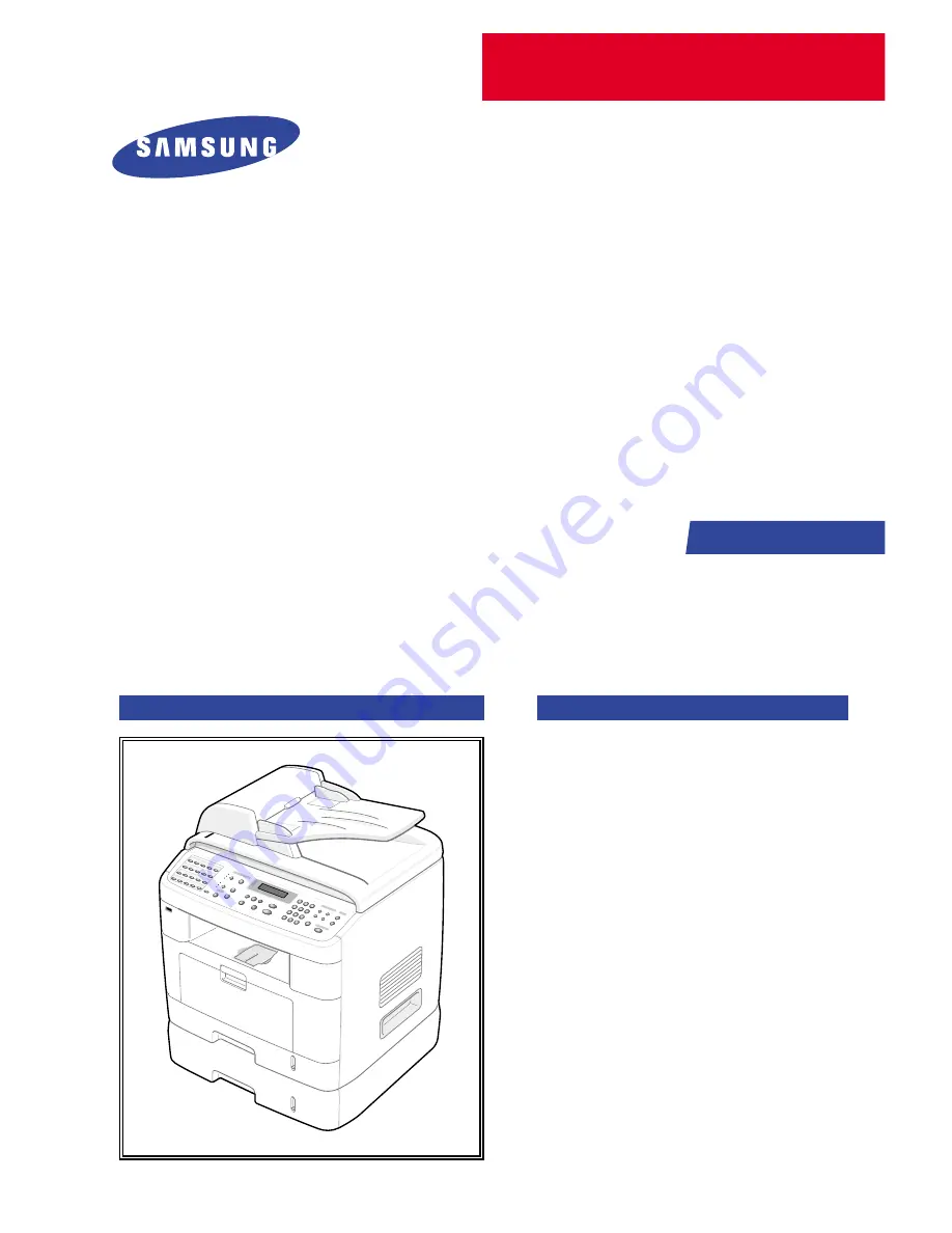
background image

SERVICE

DIGITAL LASER MFP

SCX-4720F Series
SCX-4720F
SCX-4520

Manual

DIGITAL LASER MFP

CONTENTS

1.

Precautions

2. Reference 

Information

3.

Specifications

4.

Summary of product

5.  Disassembly and Reassembly 

6. Alignment 

and 

Adjustments

7.

Troubleshooting

8.

Exploded Views and Parts List

9.

Block Diagram

10. Connection Diagram

11. Schematic Diagram

Summary of Contents for SCX-4520

Page 1: ... DIGITAL LASER MFP CONTENTS 1 Precautions 2 Reference Information 3 Specifications 4 Summary of product 5 Disassembly and Reassembly 6 Alignment and Adjustments 7 Troubleshooting 8 Exploded Views and Parts List 9 Block Diagram 10 Connection Diagram 11 Schematic Diagram ...

Page 2: ...any human access to laser radiation above a Class I level during normal operation user maintenance or prescribed service condition Warning Never operate or service the printer with the protective cover removed from Laser Scanner assembly The reflected beam although invisible can damage your eyes When using this product these basic safety pre cautions should always be followed to reduce risk of fir...

Page 3: ...g or removing the power connector The power connector must be inserted com pletely otherwise a poor contact could cause overheating possibly leading to a fire When removing the power connector grip it firmly and pull 7 Take care of the power cable Do not allow it to become twisted bent sharply round corners or otherwise damaged Do not place objects on top of the power cable If the power cable is d...

Page 4: ...rry out the following procedures before dismantling the printer or replacing any parts 1 Check the contents of the machine memory and make a note of any user settings These will be erased if the mainboard or network card is replaced 2 Ensure that power is disconnected before servicing or replacing any electrical parts 3 Disconnect printer interface cables and power cables 4 Only use approved spare...

Page 5: ... you can get harm 3 When you move the printer This printer weighs 15 6kg including toner cartridge and cassette Use safe lifting and handling techniques Use the lifting handles located on each side of the machine Back injury could be caused if you do not lift carefully 4 Ensure the printer is installed safely The printer weighs 15 6Kg ensure the printer is installed on a level surface capable of s...

Page 6: ...ctrical charges sufficient to damage ESDs 5 Do not use Freon propelled chemicals When sprayed these can generate electrical charges sufficient to dam age ESDs 6 Do not remove a replacement ESD from its protective packaging until immediately before installing it Most replacement ESDs are packaged with all leads shorted together by conductive foam aluminum foil or a compa rable conductive material 7...

Page 7: ...hooting The following tools are recommended safe and easy troubleshooting as described in this service manual DVM Digital Volt Meter Standard Indicates more than 3 digits Driver Standard type type M3 long M3 short M2 long M2 short Tweezers Standard For general home use small type Cotton Swab Standard For general home use for medical service Cleaning Equipments Standard An IPA Isopropyl Alcohol dry...

Page 8: ...FCOT First Copy Out Time F W firmware GDI graphics device interface GND ground HBP Host Based Printing HDD Hard Disk Drive HV high voltage HVPS High Voltage Power Supply I F interface I O Input and Output IC integrated circuit IDE Intelligent Drive electronics or Imbedded Drive Electronics IEEE Institute of Electrical and Electronics Engineers Inc IPA Isopropy Alcohol IPM Images Per Minute LAN loc...

Page 9: ... The Sample Pattern for the Test The sample pattern shown in below is the standard pattern used in the factory The life of the toner cartridge and the printing speed are measured using the pattern shown below The image is 70 of the actual A4 size 2 3 1 A4 5 Pattern ...

Page 10: ...Service Manual Reference Information 2 4 Samsung Electronics 2 3 2 A4 2 Pattern ...

Page 11: ...Reference Information Samsung Electronics Service Manual 2 5 2 3 3 A4 IDC 5 Patten ...

Page 12: ...Service Manual Reference Information 2 6 Samsung Electronics 2 3 4 A4 ISO 19752 Standard Pattern This test page is reproduced at 70 of the normal A4 size ...

Page 13: ...ed mark of Wi FiTM The Wi FiTM is a registered trademark of WECA Wireless Ethernet Compatibility Alliance Over 50 of a wireless LAN companies are member of it The most of main wireless networking companies are attending and the main companies are Lucent technologies Cisco Intel Symbol 3Com Enterasys Cabletron Compaq IBM Nokia Dell Philips Samsung elec tronic Sony Intersil and so on This mark certi...

Page 14: ...Service Manual Reference Information 2 8 Samsung Electronics MEMO ...

Page 15: ...e 14 8kg Gross Weight with package 20 4kg LCD 16 2 Char I O Interface USB2 0 High Speed MPU SPGPm 166MHz Power Consumption Printing Operation 370W Sleep Mode 30 W Energy Star Compliant Power Switch Yes Power Supply Input Voltage Low Voltage 110 127VAC High Voltage 220 240VAC Input Frequency 50 60Hz 3Hz Noise Printing 54dBA Copy 55dBA Standby 33dBA Warm Up Time from Cold Status Less than 42 seconds...

Page 16: ...rating 10 90 Altitude Max 8 200ft EMI Approval Class B Device Memory Standard Max 32MB 160MB Std Max 12MB PS 4MB FAX 2MB System 2MB Scan 20MB Type SDRAM Expand Memory Slot Type SDRAM DIMM Option DIMM 16 32 64 128MB SDRAM 100Pin SDRAM DIMM Use only Samsung Memory parts made Specifically for this printer Compression Technology YES Service Manual Specifications 3 2 Samsung Electronics Items SCX 4520 ...

Page 17: ...g YES Font Type 45 Scalable 1 Bitmap Number N A Power Save Yes 5 10 15 30 45min Resolution Normal 600x600dpi RET Yes 1200x1200dpi Toner Save Yes No dedicated button on CP Memory 16MB FPOT From Stand by Approx 10 seconds From LSU ON A4 From Cold Status Less than 50 seconds Duplex Print N A Printable Area 208 x 273 mm Letter Halftone Gray Scale 128levels Items SCX 4520 SCX 4720F 3 2 Print Specificat...

Page 18: ...ox 75sec USB 1 1 Color Approx 150sec USB 1 1 75dpi 300dpi Resolution Optical 600 1200dpi Enhanced 4800dpi 4800dpi Halftone 256level Scan Size Max Document Max 216mm 8 5 Width Effective Max 208mm 8 2inch Scan Width Scan to E mail Image OCR FAX WEB through PC Direct Scan to USB Memory Std Scan Depth Color 24 bit Mono 1bit for Lineart 8 Bit for Gray scale Items SCX 4520 SCX 4720F 3 3 Scan Specificati...

Page 19: ...y 1 99 Preset Yes Darkness Control 3 level by LED Copy Mode Quality Text Mixed Photo Collation Copy 600x300dpi Yes Auto return to default mode Yes Time can be changeable 15 30 60 180sec Off Changeable Default mode Contrast Image Reduce Enlarge No of Copies Special Copy N up copy 2 up 4 up Collation Copy Yes ADF only AutoFit Copy Yes Platen only 2 side Copy Yes Platen only Copy 2 side printed origi...

Page 20: ...e No Selectable in Technical Mode Pause No Yes Auto Redial No Yes Last Number Redial No Yes Distinctive Ring No Yes Caller ID No No External Phone Interface No Yes Report Tx Rx Journal No Yes List Print out Confirmation No Yes Help List No No Auto Dial List No Yes System Data List No List all user setting Sound Control Ring Volume No Yes Off Low MED HIGH Key Volume No Yes On Off Alarm Volume No Ye...

Page 21: ... LTR Rx fax duplex print out No No Multiple page scan speed No 14ppm LTR Std mode Receive Mode No Fax TEL Ans Fax DRPD Memory Capacity No 4MB Optional Memory No No Max locations No 199 locations to store to 1 Group Dial Fax Forward No Yes On Off Broadcasting No up to 209 locations Cover page No Yes Delayed fax No Yes Memory RX No Yes Functions Voice Request No No TTI No Yes RTI No Yes Polling No N...

Page 22: ... Tray 16 24 lb Bypass 16 43 lb Paper Path Standard output Bottom to Middle Front FIFO Straight Through Face up Single Sheet Paper Size Max 216 x 356mm 8 5 x14 Min 76 x 127mm 3 x5 ADF Paper Weight 12 5 28lb Capacity 50 sheets Document Size 142mm 216mm 5 6 8 5 Widtth Document Size 148 mm 356mm 5 8 14 0 Length Jam Rate Cassette 2nd Feeder 1 2000 ADF 1 1000 Multi_Feeding Cassette 2nd Feeder 1 1000 Rat...

Page 23: ...CL6 PCL5e Std PostScript Level3 Std TWAIN Yes WIA Yes RCP Yes PC FAX Yes through PC modem and Fax S W Consumables Type One Piece Type How to install Front door open and front loading Toner Life Initial 3Kpages 5 ISO Test Pattern running Standard 3Kpages High yield 5K pages Level Sensor No Toner Count Yes Dot Counter Specifications Service Manual 3 9 Samsung Electronics Items SCX 4520 SCX 4720F ...

Page 24: ...Service Manual Specifications 3 10 Samsung Electronics MEMO ...

Page 25: ...mmary of Product Service Manual 4 1 Samsung Electronics 4 4 4 Summary of Product This chapter describes the functions and operating principal of the main components 4 1 Printer Components 4 1 1 Front View ...

Page 26: ...plied with the machine It is an option that must be purchased and installed separately Option Function The network port is not fitted as standard on the machine You can purchase an optional Network Card and install it separately If your country has a different telephone connection system this socket may be blocked ...

Page 27: ...Summary of Product Service Manual 4 3 Samsung Electronics 4 1 3 Control Panel SCX 4720F ...

Page 28: ...Service Manual Summary of Product 4 4 Samsung Electronics ...

Page 29: ...ity provided with this machine Also allows you to scan and save documents in a USB flash drive and manage it when it is inserted into the USB port of your machine See User Guide Chapter 10 Installing a USB Flash Drive 3 Displays the current status and prompts during an operation Turns on when the toner cartridge is empty 4 Uses to scroll through the available options for the selected menu item Con...

Page 30: ...tarts a job 5 Selects the number of copies Allows you to use special copy features such as Clone Collation Auto Fit 2Sides on 1pg 2 4 Up multiple pages on a sheet and Poster copying Makes a copy smaller or larger than the original Allows you to save on toner by using less toner to print a document Allows you to directly print files stored on a USB flash drive when it is inserted into the USB port ...

Page 31: ...hines a light onto the OPC drum This lowers the charge on the drum s surface and improves transfer efficiency The transfer roller transfers toner from the OPC drum surface to the paper Life expectancy Over 60 000 sheets at 15 30 C 4 2 3 Driver Ass y Gear driven power unit The motor supplies power to the paper feed unit the fuser unit and the toner cartridge 4 2 4 Fixing Part Fuser The fuser consis...

Page 32: ...ss than 80ºC to protect the user and a caution label is attached where the customer can see it easily when the rear cover is opened 4 2 5 Scanner This image is read using a photosensitive sensor It consists of a CCD module Connection board ADF board AFE Analog Front End Image Processor Located in CPU platen glass and ADF mechanism CCD Module Specification 1 Resolution 600dpi A4 2 Maximum scan wide...

Page 33: ... laser light A rotating polygon mirror reflects the laser light onto the OPC and each side of the mirror is one scan line The OPC drum turns as the paper feeds to scan the image down the page The HSYNC signal is created when the laser beam from LSU reaches the end of the polygon mirror and this signal is sent to the controller The controller detects the HSYNC signal to adjust the vertical line of ...

Page 34: ...loping roller and blade Doctor blade Developing Method Non magnetic 1 element contacting method Toner Non magnetic 1 element shatter type toner The life span of toner 3 000 sheets IDC Pattern A4 standard Toner remaining amount detecting sensor Yes OPC Cleaning Electrostatic process Management of waste toner Collect the toner using a Cleaning Blade OPC Drum protecting Shutter Yes Classifying device...

Page 35: ...ORY CODE LOW 29LV160DB U30 14 CMOS LOGIC 74HCT273 U58 24 MODEM X TAL 28 224MHz OSC6 5 FLASH MEMORY P CL6 HIGH 29LV160DB U24 15 CMOS LOGIC 74HCT273 U59 25 USB HOS T X TAL 6MHz OSC9 6 FLASH MEMORY P CL6 LOW 29LV160DB U31 16 P ANAS ONIC 3V BAT 2 26 P S3 DIMM CN10 7 SDRAM K4S281632E U45 17 VARTA 3 6V BAT1 27 RAM DIMM CN12 8 SDRAM K4S281632E U46 18 FP GA EX64 FTQ64 U44 28 JACK USB J1 9 MODEM FM336 U62 ...

Page 36: ...rogram and to control whole system Main function block Completely Integrated System for Embedded Applications 32 Bit Risc Architecture Efficient and Powerful ARM9 Core LSU Interface Module for Interfacing PVC or HPVC with LSU 2 Channel General Purpose DMA Controller for High Speed I O Dual Memory Bus Architecture Operation Frequency AHB Bus 60MHz Internal System Bus 120MHz Operation Voltage 3 3V P...

Page 37: ...m Program by PC INTERFACE FAX for Journal List and Memory for One Touch Dial Speed Dial List size 4M Byte Access Time 70 nsec 4 3 4 SDRAM SDRAM is used as Swath Buffer in Printing Scan Buffer in Scanning ECM Buffer in FAX receiving and System Working Memory Area size 32MB 32Mbyte Basic Max Frequency 133MHz store Fax Receive Memory Data by using Battery 4 3 5 Battery Backup SCX 4720F only Backup po...

Page 38: ...tects that paper exits cleanly from the Machine using an exit sensor CON2 24 on the engine board and actuator on the frame The monitors signal P_EXIT and detects the on off time of the exit sensor and if jam status is detected then JAM2 is displayed the on the LCD panel 5 Cover Open Senser The Cover open sensor actuator is located on the front cover and the senor is in the main frame When the fron...

Page 39: ... 12V and 24V supplies to the main and other PBAs The HVPS creates the high voltage of THV MHV Supply Dev and supplies it to the toner cartridge The CPU is used to modify some of these voltage settings to provide the ideal voltages to create the image The HVPS part uses the 24V and outputs the high voltage for THV MHV BIAS and the outputted high voltage is supplied to the toner OPC cartridge and tr...

Page 40: ...LSU Laser Scanning Unit When printing the exposed voltage on the OPC is 180V unexposed is 900 1000V and the exposing voltage on the DEV is 430V Therefore toner with polarity is developed onto an exposed section of the OPC Output voltage 430V DC 20V Error a If DEV is GND print density gets extremely low b When DEV is floating due to poor connection between the frame and cartridge contacts etc print...

Page 41: ...fluctuating range AC 198V 264V AC 90V 135V AC 198V 264V Rated Frequency 50 60 Hz Frequency Fluctuating range 47 63 Hz Input Current Under 5 0Arms 2 5Arms When the fuser lamp is off and input output voltages are in range 2 Rated Output Power 3 Power Consumption 4 Length of Power Cord 1830 50mm 5 Power Switch Fitted NO ITEM CH2 CH3 Remark 1 CHANNEL NAME 5V 24 0V 2 CONNECTOR PIN CON 23 CON 23 5V PIN ...

Page 42: ...heated using AC power The AC power is controlled by a Triac THY1 a semiconductor switch On Off control is achieved when the gate of the Triac is turned on off by a Photo triac PC1 this is an insulting part In the other words the AC control part is a passive circuit It turns the heat lamp on off by taking a signal from the engine control section When the HEATER ON signal is activated by the engine ...

Page 43: ...e paper passes the feed sensor the trailing edge of the paper does not pass the feed sensor within certain time During this time the feed sensor cannot be Off After the leading edge of the paper passes the feed sensor the paper does not reach the exit sensor within cer tain time The exit sensor cannot be On during this time There is already paper between the feed sensor and the exit sensor 4 5 1 3...

Page 44: ...using The temperature of the heat roller s surface is detected according to the resistance value of the thermistor The thermistor resistance is measured using the A D converter and thus the CPU can determine the temperature of the heat roller The AC power is controlled by comparing the target temperature to the value from the thermistor If the value from the thermistor is out of the controlling ra...

Page 45: ...ve to be used in conjunction with the USB Direct printing and Scan to USB functions 4 6 OPE PBA The OPE board consists of various function keys and an LCD to display set status and operator messages A MICOM HOLTEC HT48R50 drives the LEDs and LCD Communication between the OPE and the CPU on the main board is serial related signals are Reset TXD and RXD ...

Page 46: ...erface Unit LIU V 34 Half Duplex Mode V 90 PCM V 34 Duplex Data Modes V24 Interface FM336 Modem Crystal OR Oscillator Line Interface telephone line TIP RING Optional Eye Pattern Generator Speaker Amplifier Power Supply Host Processor RTS XTLI XTLO CLKIN RIN TXA1 TXA2 DH RINGD TALK EYEXY EYESYNC EY RCLK SPKR SV 3 3V AGND DGND CTS TXD TDCUK XTCLK RLSD RXD RDCLK DTR DSR RI RD WR CS D x 0 RS 4 0 IRQ R...

Page 47: ... to the impedance of the receiving telephone line and a circuit to isolate the fax machine from the PSTN and a surge absorber to protect against lighting strike surges on the incoming line The Telephone circuit is consists of ring detection circuit speech circuit external hook detection circuit and recall circuit 4 5 6 2 3 1 1 TRANS MATCHING T1 2 TRANS MATCHING T2 3 RELAY RE1 4 VARISTOR VAR1 VAR2 ...

Page 48: ...odular Plug RJ 11C Arr1 Arr2 and Arr3 are protection components to prevent damage due to overvoltage surges e g lightening 4 8 4 Transformer Circuit The Transformer circuit is a line impedance matching circuit which matches the internal impedance of the fax machine to the external 48Volt DC impedance of the PSTN system The Transformer circuit insolates the fax machine electrically from the PSTN ...

Page 49: ...t 20mA 100mA Pseudo Ring Sound Ring frequency 750Hz 1020Hz Ring Interrupt period Mark Space controlled by CPU Modem 4 8 6 Off Hook State DC Resistance DP Dial Mode DC 30mA 50 220 Ω DTMF Dial Mode DC 20mA 50 300 Ω DTMF Dialing DC 20mA 50 540 Ω Matching Input AC Impedance 600 Ω 30 for 300Hz 3 4KHz Minimum Line Current detecting Off Hook 20mA Handset Hook Off 15mA external Handset Hook Off Minimum Li...

Page 50: ... of Product 4 26 Samsung Electronics 4 8 7 Signal Input Signal Level Range 0dBm 48dBm DP Dial Pulse Dial Make Brake Ratio 40 60 Pulse Speed 10 0 8 pps Minimum Pause above 60 msec DTMF Signal Coding Format Transmission Level ...

Page 51: ...Summary of Product Service Manual 4 27 Samsung Electronics MEMO ...

Page 52: ...routing that will be affected Whenever servicing the machine you must perform as follows 1 Check to verify that documents are not stored in memory 2 Be sure to remove the toner cartridge before you disassemble any parts 3 Unplug the power cord 4 Use a flat and clean surface 5 Replace only with authorized components 6 Do not excessive force on components made of plastic they may break 7 Make sure a...

Page 53: ...ics 5 2 Rear Cover 1 Remove the four screws securing the Rear Cover 2 Remove the Rear Cover from the Frame Ass y and Scanner Ass y 3 Unclip the Face Up Cover from the Rear cover as shown below Then lift the Face Up Cover out Rear Cover Face Up Cover ...

Page 54: ...see page 5 2 2 Take out the Cassette 3 Open the front cover and remove 2 screws on the front and 1 screw on the back Release 3 clips under neath ease the rear screw bracket over its locating pin and pull the RH side cover to the right taking care not to damage the clips to remove it from the Frame Assembly Side Cover LH Side Cover RH Cassette ...

Page 55: ...anual Precautions 5 4 Samsung Electronics 5 4 Front Cover 1 Open the Front Cover 2 Remove the Toner Cartridge 3 Unclip the Front Cover from the Frame Ass y Then remove the Front Cover as shown below Front Cover ...

Page 56: ... 5 3 2 Remove the 2 screws securing the Scanner Ass y as shown below 3 Remove the 5 connectors and the ground wire screw from the main PBA as shown below 4 Pull up the Scanner Ass y as shown below 5 SCX4520 only Lift the Platen Cover upward to remove it 3 1 2 Scanner Ass y Precautions Service Manual 5 5 Samsung Electronics ...

Page 57: ...m the frame 7 Lift the front part of the COVER OPE FRONT to release the hook connecting the cover with the scan assembly SCX 4520 SCX 4720F 8 Release the 3 clips on the front of the OPE unit and remove the OPE unit as shown below taking care to thread the cable harness through the frame SCX 4520 SCX 4720F COVER OPE FRONT COVER OPE FRONT Clips Clips ...

Page 58: ...Ass y by releasing 2 clips on each side then pull the Scan Upper upward and remove it 11 Remove the CCD Cable as shown below 12 Pull up the CCD Shaft and take out the Scanner Module 13 Squeeze the spring to release the tension in the Belt and lift from the pulleys as shown below CCD Cable Scanner Module CCD Shaft Scan Upper Spring Belt ...

Page 59: ...ssible as shown on the right Caution 14 Remove the Reduction Gear and Idle Gear as shown below Caution Reassembling Scanner Module 1 When re fitting the scanner belt and belt spring take care to relocate the tension spring as close to the right hand side of the scanner module as is possible as shown on the right 2 When refitting the Scan Upper cover take care to ensure that the cover open switch i...

Page 60: ...lectronics 15 Remove the 3 screws and take out the Motor Bracket 16 Unplug the connector from the Open Sensor Ass y 17 Unlatch the Open Sensor and remove it as shown below 18 Remove the CCD lock Open Sensor Unlock Lock CCD Lock Motor Bracket ...

Page 61: ...hen working on the ADF Motor Ass y take care not to contaminate any of the rubber surfaces with grease 4 Release the Bush and rotate it until it reaches the slot as shown below Then lift the Pick Up Ass y out 5 Remove the 2 screws securing the Upper Cover and remove it as shown below Caution Before removing the ADF Motor Ass y take great care to note the position of the ferrite core and the motor ...

Page 62: ...the ADF Motor Ass y Note It is not necessary to disassemble the ADF unit in order to change the ADF separator pad Simply open the ADF cover and remove the Pickup Ass y step 4 page 5 10 Then using a pair of tweezers or a small flat bladed screwdriver release the clips on each side of the ADF Separator Pad Ass y ADF Lower Ass y ADF Motor Ass y ...

Page 63: ...OPE Unit you should remove Rear Cover see page 5 2 Side Cover LH RH see page 5 3 Scanner Ass y see page 5 5 2 Remove the 7 screws securing the OPE PBA from to the OPE Cover 3 Remove the Contact Rubber from the OPE Cover 4 Remove the Key Pad from the OPE Cover OPE Cover OPE PBA Contact Rubber Key Pad ...

Page 64: ...E Unit you should remove Rear Cover see page 5 2 Side Cover LH RH see page 5 3 Scanner Ass y see page 5 5 2 Remove the 10 screws securing the OPE PBA from to the OPE Cover 3 Remove the Contact Rubber from the OPE Cover 4 Remove the Key Pad from the OPE Cover OPE Cover OPE PBA Contact Rubber Key Pad ...

Page 65: ...r LH RH see page 5 3 Scanner Ass y see page 5 5 2 Remove the 4 screws securing the Middle Cover and remove it 3 Remove 2 screws securing the Controller Shield Ass y to the Middle Cover Unclip the Middle Cover from the Frame Ass y as shown below Take care to release the Shield Ass y locating pegs and lift the Top Cover out 4 Remove the Exit Gear and Bearing as shown below Middle Cover ...

Page 66: ...he connectors and the 5 screws con necting the Controller Shield Assembly to the Middle Cover and frame and remove the assembly 3 If fitted remove the 2 screws connecting the NIC card to the Controller ShieldAssembly and remove the card 4 Remove 3 screws to remove the bracket from the main board Controller Shield Ass y Main Board Bracket NIC Card 5 9 Controller Shield Ass y ...

Page 67: ... 2 Unplug the Exit AC and Fan connectors Unplug the LIU connector if fitted 3 Remove the 11 screws securing the Engine Shield Ass y and tilt to one side Then unplug the all the HVPS SMPS harness before removing the ass y 4 Remove the 2 screws to remove the exit board Engine shild Ass y Main Connector Exit Connector AC Connector Fan Connector Exit Board 5 10 Engine Shield Ass y Exit Board ...

Page 68: ...ge 5 3 Scanner Ass y see page 5 5 Engine Shield Ass y see page 5 16 2 Remove the 2 screws securing the Inlet Bracket and remove it 3 Remove the one screw securing the Engine Shield ground wire 4 Remove the 3 screws securing the SMPS Then lift the SMPS out as shown below 5 Remove the 3 screws securing the LIU Then lift the LIU out as shown below Inlet Bracket SMPS ...

Page 69: ...crews securing the Fuser Ass y and remove it 3 Remove the 2 bolts securing the Thermostat Then lift the Thermostat out taking care not to loose the 2 nuts 4 Remove the 2 screws securing the Halogen Lamp Then take out the Halogen Lamp from the Heat Roller 5 Remove 4 screws to remove the fuser cover as below Remove 2 screws to remove the guide input Fuser Ass y Thermostat Bolts Nuts Heat Roller Halo...

Page 70: ...ow 7 Remove the one screw securing the Thermister and remove it as shown below Thermistor Thermistor 5 13 Fan 1 Before you remove the Fan you should remove Rear Cover see page 5 2 Side Cover RH see page 5 3 2 Unplug the connector from the SMPS and remove the one screw Then take out the Fan DC Fan ...

Page 71: ... Remove the 4 screws securing the LSU and remove it 3 Unplug the two connectors 5 14 LSU 1 Before you remove the CRUM Board you should remove Rear Cover see page 5 2 Side Cover LH RH see page 5 3 Scanner Ass y see page 5 5 Front Cover see page 5 4 Middle Cover see page 5 14 LSU see page 5 20 2 Remove the 4 screws to separate the CRUM board from the main frame as below taking care not to loose the ...

Page 72: ...ers stamped into the Drive Ass y base plate When refitting the Drive Ass y tighten the screws the order they are numbered Only screw s numbered 1 to 5 are fitted at this stage Screw 6 is fitted when the Shield Controller Ass y is refitted 5 17 Cover Mid Front 1 Before you remove the Cover Mid Front you should remove Rear Cover see page 5 2 Side Cover LH RH see page 5 3 Middle Cover see page 5 14 2...

Page 73: ...e 5 20 Cover Mid Front see page 5 22 2 Remove the 3 screws securing the Transfer Earth and remove it 3 Unplug the PTL Holder connector then remove the PTL Holder and PTL Lens as shown below 4 Remove the transfer roller by pressing the hook securing the roller to the right using a tool 5 Unlatch the Bushing and remove it Then lift the Transfer Roller out as shown below Transfer Earth PTL Holder PTL...

Page 74: ...Middle Cover see page 5 14 Controller Shield Ass y see page 5 15 Drive Ass y see page 5 20 2 Remove the 4 screws securing the Guide Paper Front and remove it 3 Remove the screws on the right and left sides of the guide paper to remove the guides and the spring as shown below 4 Remove the 3 screws securing the Feed Bracket and remove it 5 Remove the Feed Gear2 Guide Paper Front Guide Paper Spring S...

Page 75: ...Service Manual Precautions 5 24 Samsung Electronics 6 Remove the Feed Gear1 Ass y 7 Pull up the Feed Roller and Feed Roller1 Feed Gear1 Ass y Feed Roller Feed Roller1 ...

Page 76: ...k Up Gear Ass y 3 Take out the Pick Up Ass y as shown below 4 Remove the 2 screws securing the Manual Solenoid and Pick Up Solenoid Then remove Manual Solenoid and Pick Up Solenoid 5 To replace the pick up roller move the stopper secur ing the sponge roller to the right and then turn the sponge roller to remove it from the shaft When replacing either the MP pick up roller or main cassette pick up ...

Page 77: ...ible 3 Slide the white collar as far to the side as possible 4 Slide the Pickup Roller as far as possible to the side until it is free from the white collar on the other end 5 Rotate the Pickup Roller around the drive shaft until it can be removed b In order to replace the MP Pickup Roller 1 Release the white catch and slide the locking piece as far to the side as possible 2 Slide the white collar...

Page 78: ...erns Much of this chapter is also included in the user s guide 6 1 Paper path Scanner Part PTL PIC K R PR CR DR SR TR FR OPC L S U Fuser Toner Cartridge 1 2 3 4 5 6 8 7 Sensor Doc Sensor Doc Sensor Doc ADF Roller Pickup Roller Exit Roller Doc Paper 30Sheets ADF Idle Roller Sensor R Sensor Regi gi Feed Roller CCD Module White Sheet hite Sheet White Sheet Sensor Regi Sensor Scan Sensor Scan Sensor S...

Page 79: ...hin a certain time 4 The paper then passes through the paper exit sensor and out of the set Jam 2 occurs if the trailing edge of the paper does not pass the exit sensor within a certain time of the paper leading edge activating the exit sensor Scanner Part CCD Module White Sheet White Sheet 1 2 3 4 8 5 6 7 5 6 7 Sensor Scan Sensor Regi Feed Roller 8 Exit Roller 1 2 3 4 Doc Paper 50 Sheets Pickup R...

Page 80: ...echanism causing print quality problems or possibly electrical shock Sensor Doc Sensor Doc ADF Roller Pickup Roller Exit Roller Doc Paper 30Sheets ADF Idle Roller Sensor Regi Feed Roller White Sheet White Sheet Sensor Regi Sensor Scan Sensor Scan Document Jam in the ADF area PTL PIC K R PR CR DR SR TR FR Empty Sensor OPC L S U Fuser Toner Cartridge EXIT Sensor Feed Sensor MP Sensor Paper Jam0 in t...

Page 81: ...the ADF Automatic Document Feeder DOCUMENT JAM appears on the display 6 2 1 1 ADF Input Misfeed 1 Open the ADF top cover 2 Pull the document gently to the right and out of the ADF 3 Close the ADF top cover Then load the documents back into the ADF NOTE To prevent document jams use the document glass for the thick thin or mixed documents ...

Page 82: ...t from the ADF or the feed area by carefully pulling it towards the right by using both hands 3 Close the document cover Then load the documents back into the ADF 6 2 1 2 ADF Exit Misfeed 1 Open the document cover and turn the release knob to remove the misfed documents from the exit area 2 Close the document cover Then load the documents back into the ADF 6 2 1 3 ADF Roller Misfeed ...

Page 83: ...not exit continue to Step 2 2 Pull the paper tray open 3 Remove the jammed paper by gently pulling it straight out If there is any resistance and the paper does not move when you pull or if you cannot see the paper in this area skip to the fuser area around the toner cartridge 4 Insert the paper tray into the machine until it snaps into place 5 Open and close the front cover to resume printing ...

Page 84: ... the Toner Cartridge Area NOTE The fuser area is hot Be careful when removing paper from the machine 1 Open the front cover and remove the toner cartridge 2 Remove the jammed paper by gently pulling it straight out 3 Replace the toner cartridge and close the front cover Printing automatically resumes ...

Page 85: ...the machine If the paper does not exit continue to Step 2 2 Gently pull the paper out of the front output tray 3 If there is any resistance when you pull the paper or the paper is not seen in the front output tray open the rear cover 4 Remove the jammed paper by gently pulling it straight out 5 Close the rear cover 6 Open and close the front cover to resume printing ...

Page 86: ...am appears on the display when you try to print using the manual feeder and the machine does not detect paper due to no paper or improper paper loading The error message may also occur when the paper is not properly fed into the machine through the manual feeder In that case pull the paper out of the machine ...

Page 87: ...etup Change Default Timeout 6 Reports System Data 8 Machine Setup Language Power Save CCD Power Save USB Mode 9 Maintenance Clean Drum Clear Memory 6 3 User Mode SCX 4520 The table below shows the map of User settings available in User Mode These are fully described in the User Guide and are not included here ...

Page 88: ...d Toll Save Junk Fax Setup Secure Receive Prefix Dial No Stamp RCV Name ECM Mode 6 Reports Phone Book Send Report RCV Report System Data Scheduled Jobs Tx Confirm Junk Fax List 7 Sound Volume Speaker Ringer Key Sound Alarm sound 8 Machine Setup Machine ID Date Time Clock Mode Dial Mode Language Power Save CCD Power Save USB Mode 9 Maintenance Clean Drum Notify toner Clear Memory 6 3 User Mode SCX ...

Page 89: ...d perform various tests to help with failure diagnosis When in Tech mode the machine still performs all normal operations While in Tech mode the machine still performs all normal operations To enter the Tech mode To enter the Tech mode press in sequence and the LCD briefly displays TECH the machine has entered service tech mode 6 4 2 Setting up System in Tech Mode ...

Page 90: ...elect the rate between 5 and 10 CLEAR ALL MEMORY The function resets the system to factory default settings This function is used to reset the system to the initial value when the product is functioning abnormally All the values are returned to the default values and all the information which was set by the user will be erased Method 1 Select the MEMORY CLEAR in TECH MODE 2 Push the ENTER button 3...

Page 91: ...r upgrade Ensure you save ALL of these files in the same folder 2 At the DOS prompt enter the correct command as shown below and push the enter key Then the upgrade will automatically take place 3 There are two commands use the correct one depending on the condition of the set When the product is in the idle condition down rom file When the product is in Ready condition TECH MODE DATA SETUP FLASH ...

Page 92: ...feature to test the machine s ROM The result and the software version appear in the LCD display FLASH VER 1 00 V ENGINE VER 1 00V PATTERN TEST Using this pattern printout you can check that the printer mechanism is functioning properly This function is for factory manufacturing use only SHADING TEST The function is used to set the optimum scan quality determined by the specific characteristics of ...

Page 93: ...ROTOCOL LIST This list shows the sequence of the CCITT group 3 T 30 protocol during the most recent sending or receiving operation Use this list to check for send and receive errors If SYSTEM DATA This list provides a list of the user system data settings and tech mode settings ...

Page 94: ...est 1 On 2 Off next test selected 1 1 LSU Motor Test 1 On 2 Off next test selected 2 LSU Hsync Test 1 On 2 Off next test selected 3 LD Test 1 On 2 Off next test selected 2 1 Feed Sensor Test 1 Check read the sensor 2 Next Next Sensor test 2 Exit Sensor Test 1 Check read the sensor 2 Next Next Sensor test 3 Cover Sensor Test 1 Check read the sensor 2 Next Next Sensor test 4 Empty Sensor Test 1 Chec...

Page 95: ...rts and Laser Ready is displayed if Laser Leady On Off the motor spins at the correct speed otherwise Laser Error is displayed 13 LD Test Diode On is displayed when the laser diode is on Diode On Off Otherwise Diode Off is displayed 21 Feed Sen Test These functions allow the current state of the sensor to be Sensor Off or Sensor On 22 Exit Sen Test displayed 23 Cover Sen Test This function allows ...

Page 96: ...counters The time the machine was first used is also displayed These settings are remembered after memory delete Clear All Memory Method Press MENU 1 9 3 in sequence The Firmware version is displayed on the LCD Press 1 in the number keypad The LCD display shows Updated date Press 2 in the number keypad The LCD display shows Product first use date Alignment Adjustments Service Manual 6 19 Samsung E...

Page 97: ...or maintenance purposes and is for reference only Environmental conditions temperature humidity dust etc and actual use can cause these figures to vary COMPONENT REPLACEMENT CYCLE ADF Rubber 20 000 Pages Pick up Roller 150 000 Pages Friction Pad 60 000 Pages Transfer Roller 60 000 Pages Fuser Unit 80 000 Pages Toner Cartridge 3 000 Pages A4 ISO 5 Pattern ...

Page 98: ...l image period Kind of abnormal image 1 OPC Drum 75 5mm White spot Block spot 2 Charge Roller 37 7mm Black spot 3 Supply Roller 44 9mm Horizontal density band 4 Develop Roller 35 2mm Horizontal density band 5 Transfer Roller 47 1mm Black side contamination transfer fault 6 Heat Roller 77 8mm Black spot and fuser ghost 7 Pressure Roller 75 4mm Black side contamination PTL PIC K R PR CR DR SR TR FR ...

Page 99: ...Meaning There is a problem in the fuser unit Solution Check thermostat thermister contact point Heating Lamp Over Heat Meaning The printer has overheated Solution Your unit will automatically return to the standby mode when it cools down to normal operating temperature If failure persists check the ELA HOU FUSER Delayed Function Full Only SCX 4720F Meaning The delayed fax job list or memory space ...

Page 100: ...to make sure a fax can be received No Not Assigned Only SCX 4720F Meaning YThe speed dial location you tried to use has no number assigned to it Solution Dial the number manually using the number keypad or assign the number No Not Available Only SCX 4720F Meaning You have tried to delete the number for a delayed fax job Solution Verify the number to be deleted and try again Or Delete the number af...

Page 101: ...hine does not have enough memory space to complete the operation you are attempting Solution Reconfirm the remote machine s features Jam 1 or No Cartridge Meaning Paper has jammed in the paper exit area Or the toner cartridge is not installed Solution Clear the jam Or install the toner cartridge Line Busy Only SCX 4720F Meaning The receiving party did not answer or the line is already engaged Solu...

Page 102: ...Check and Cause Solution 1 Check the Solenoid by using Tech Mode 2 Check cassette MP knock up plate and springs 3 Check paper separator pad 4 Check the pick up roller for contamination and correct assembly 5 If continuous clusters occur check all rollers between pickup and registration sensor 6 If the paper feeds into the printer and Jam 0 occurs perform Tech Mode to check feed sensor 1 Replace th...

Page 103: ...nated with toner 1 Check if the exit sensor actuator is defective Check if the actuator exit is deformed Check if the lever part is deformed Check whether burrs occur in the assembly part of the exit actuator and if the actuator operates smoothly Check if foreign objects or paper debris are preventing the correct operation of the actuator 2 If the paper is stuck in the fuser disassemble the fuser ...

Page 104: ...bber with a soft cloth dampened with IPA Isopropyl Alcohol or water 4 Use paper with a smother surface finish 7 1 6 Paper rolled in the fuser Description Paper rolled around fuser rollers or Concertina jam Check and Cause Solution 1 Contamination of the pressure roller or heat roller 2 Damaged or deformed ribs claws or springs 1 After disassembling the fuser clean contamination from between the he...

Page 105: ... set taking care not to touch the green surface Use the gearwheel at the side to rotate the OPC drum and pull the paper from the cassette Clean fingerprints on the OPC gently with soft tissue taking care not to scratch the surface 7 1 8 Defective ADF Description ADF Automatic document Feeder does not operate correctly Check and Cause Solution 1 Check if the ADF rubber or HOLDER rubber are damaged ...

Page 106: ...gain after clearing the memory 2 If re connecting the harness does not correct the fault replace the OPE Ass y and the main Board in sequence 7 2 2 Defective OPE Keypad Description Pressing keys does not cause the set to respond correctly Check and Cause Solution 1 Clear the memory See page 6 18 2 Check that there is an audible key click when a key is pressed 1 Check that the keypad is assembled c...

Page 107: ...d in the LCD panel even when paper is loaded in the cassette Check and Cause Solution 1 Deformed paper sensor actuator or faulty sensor 2 SMPS PBA or Main PBA is defective 3 Faulty cables or connectors 1 Replace the defective actuator or sensor 2 Replace the SMPS PBA or MAIN PBA as appropriate 7 2 5 Paper Empty without indication Description The paper empty message does not appear in the LCD when ...

Page 108: ...tion Check and replace switch if necessary 2 Replace the Main Control board or Cover Open S W as necessary 7 2 6 Cover Open Description The Cover Open message appears on the LCD even when the print cover is closed Check and Cause Solution 1 The Open Cover microswitch may be stuck or faulty 2 The tab on the front cover may be damaged or broken 3 Check the connector and cables between Switch and mai...

Page 109: ...on 1 The main motor harness or Motor PCB may be faulty 1 Check the motor harnesses and connectors replace if defective If the problem persists replace the main PBA Note Check motor operation using EDC Mode 7 2 9 No Power Description When system power is turned on the LCD panel does not come on Check and Cause Solution 1 Check if the power input and SMPS output are normal 2 LCD panel does not come ...

Page 110: ...n 1 1 Contamination of the window or internal lenses of LSU mirror 2 Foreign object inside the toner cartridge or low toner 3 Foreign object contamination or burr on the edge of the toner cartridge window 4 If the fuser is defective voids occur periodically at the top of a black image 5 Contamination of the OPC drum 6 Depression or deformation of the surface of the transfer roller 1 Clean the LSU ...

Page 111: ...ts occur periodically in the printing Digital Printer Digital Printer Digital Printer Digital Printer Digital Printer Check and Cause Solution 1 If dark or blurry black spots occur periodi cally the rollers in the Developer may be contaminated with foreign matte or paper particles Charge roller 37 7 mm interval OPC drum 75 5 mm interval 2 If faded areas or voids occur in a black image at intervals...

Page 112: ... print out again 3 Wait 30 minutes after printer is powered on before you start printing 4 Clean the cartridge and set contacts Generally clean dirt from inside the set 5 Replace the HVPS if the problems are not solved by the above four instructions 7 3 6 Dark Image or a Black Description The printed image is dark Digital Printer Digital Printer Digital Printer Digital Printer Digital Printer Chec...

Page 113: ...ption Light dark background appears in whole area of the printing Digital Printer Digital Printer Digital Printer Digital Printer Digital Printer Check and Cause Solution 1 Printing large quantities of low coverage 2 pages or the printer has not been used for a long time 2 Is a recycled toner cartridge be used 3 Has the life span of the toner cartridge ended 4 Is the movement Up and Down of the tr...

Page 114: ... blade in the toner cartridge 1 and 2 Clean all HV contacts If problem persists replace the HVPS If problem still persists replace the Main PBA 3 Replace the toner cartridge and try to print out 4 Check the transfer roller lifetime and replace it 5 Wait about 30 minutes after power on before using printer 6 Replace the toner cartridge and try to print out again 7 3 10 Ghost 2 Description Ghost occ...

Page 115: ...ion 1 Toner leakage due to improperly sealed toner cartridge 2 If the transfer roller is contaminated stains on the face of page will occur 1 Replace the toner cartridge 2 If the transfer roller is contaminated run PC Cleaning Mode Print 2 or 3 times and then perform Self Test 2 or 3 times to remove contamination 7 3 12 Ghost 4 Description A White ghost occurs in a black image printing at 32 mm in...

Page 116: ...Pressure roller Check and clean the area between the H R and the Thermistor Caution Take care not to deform the rollers 7 3 15 Blank Page Print out 1 Description Blank page is printed Check and Cause Solution Bad ground contacts in OPC and or toner cartridge 1 Check if the Ground OPC or the OPC Ground Zener diode are defective or open circuit set inside left side 2 Remove contamination of the term...

Page 117: ...BA replace as necessary 4 Use Tech mode Modem Test to check that the speaker and amplifier are working Replace the Main B d 7 4 2 Defective MF DIAL Description The MF DIAL is not functioning Check and Cause Solution 1 Check that the telephone line cord supplied with the set is connected to TEL LINE correctly 2 Listen for a CLICK sound when the keKEY is pressed 3 Check the connection of the HARNESS...

Page 118: ...ODEM shows a fault replace the Main B d 7 4 4 Defective FAX FORWARD Description RECEIVE is functioning but FORWARD is not functioning or received data is corrupt Check and Cause Solution 1 Check if there is a NOISE line by pressing on hook dial and listening 2 Check that the destination fax machine can receive forwarded faxes by using a different sending fax machine preferably from the same wall s...

Page 119: ...se Solution 1 Check if there is a NOISE line by pressing on hook dial and listening 2 Ask sender to send to another fax machine if possible connected to the same wall socket 1 If you can hear a noisy line when using on hook dial replace or repair the telephone line 2 Replace LIU or main PBA in sequence Check and Cause Solution Check that the RECEIVE Mode is set to FAX MODE If the fault persists ev...

Page 120: ...working Check and Cause Solution Check the FAX status of the forwarding side This is a problem with the sending fax machine Correct the setting on the remote machine Check and Cause Solution 1 Check that the RECEIVE Mode is set to FAX MODE 1 If the RECEIVE Mode is set to the TEL MODE reset it to the FAX MODE 2 Even after the RECEIVE Mode is changed to the FAX Mode the problem persists then try to ...

Page 121: ...d Cause Solution 1 Check for CCD problem on the Main PBA 2 Check shading profile 1 Check the CCD harness is properly connected 2 Redo shading profile in the tech mode Check and Cause Solution 1 Check the Scanner Cover is properly closed 2 Check shading profile 3 Check white black reference voltage on Main PBA 1 Room light can pass through a thin original 2 Redo shading profile in the tech mode 3 R...

Page 122: ...ly light or dark Check and Cause Solution 1 Check shading profile 2 Check the gap between original and scanner glass 3 Check printing quality 1 Redo shading profile in the tech mode 2 A gap of more than 0 5 mm can cause a blurred image Ensure rollers and cover close correctly Replace as necessary 3 See Print troubleshooting 1 Check for correct assembly of gears and motor Ensure no parts are foulin...

Page 123: ...e par allel port is properly configured in the BIOS 2 If printing is OK check that the Scan driver is also installed Refer to User s Manual 3 If the copy function works replace the Main PBA If the copy function doesn t work replace the CCD Ass y and try again 7 6 2 Poor Quality of PC Scanned images Description The image PC scanned is not clear or bad Check and Cause Solution 1 Use TECH mode to car...

Page 124: ... the toner cartridge however you should replace the toner cartridge to solve the problem permanently 7 7 2 1 Redistributing Toner When the toner cartridge is near the end of its life white streaks or light print occurs The LCD displays the warning mes sage Toner Low You can temporarily reestablish the print quality by redistributing the remaining toner in the cartridge 1 Open the Front Cover 2 Lig...

Page 125: ...or life expired replace the cartridge 7 7 4 2 Toner Empty Explanation The toner cartridge is empty Solution Replace the cartridge 7 7 4 3 Drum Warning Explanation This message appears when the OPC drum is nearing the end of its life 14 000pages This means that the life of the mechanical parts in the cartridge has expired this is not an indication of toner remaining Solution After printing about 15...

Page 126: ... intervals a Check the distance between contamination marks b Check the appearance of both ends of the toner cartridge OPC drum 2 Random page contamination a Check that the terminals contact points of the toner cartridge and the set are clean b Check that the terminals contact points of the toner cartridge and the set are not damaged 1 All of 1 2 3 If image quality improves by shaking replace with...

Page 127: ...oner cartridge and the set are clean b Check that the terminals contact point of the toner cartridge and the set are not damaged 1 For item 1 Run OPC Cleaning Mode Print 4 5 times repeatedly to remove excess toner Especially check for foreign substances on the OPC surface Clean with a clean gauze moistened with IPA Isopropyl Alcohol take care not to damage the OPC surface Never use other forms of ...

Page 128: ...ct of the toner cartridge or set b Check if the terminal assembly is normal Especially check the charge roller terminal 3 The printed image is dark and ghost occurs a Check if foreign substances are stuck to the terminal point of contact of the toner cartridge or set b Check if the terminal assembly is normal Especially check the developer roller terminal 1 All of Items 1 2 3 a Clean the contacts ...

Page 129: ...n between PC and printer port are correcct If you use windows check that the printer driver in the controller is set up correctly set up the correct port is selected and Use On line is selected in the driver If the printer driver is properly set up try printing a test page from the driver proper ties Check in which program printing is not working Try opening Memo Pad and printing If the printer is...

Page 130: ...ns there is a hard disk space problem rather than a printer RAM problem In this case pro vide more space on the hard disk Secure more space using the disk utilities program 2 The connection of the cable and printer port is not correct Check that the cable is properly connected and if you are using the parallel port check that the port settings in CMOS is correct 3 For the printer port Select ECP S...

Page 131: ...irtual memory this is caused by insufficient space on the hard disk 1 Ensure that ECP best or SPP is selected in the CMOS BIOS setup 2 Ensure that the correct driver is loaded Use the driver supplied on the CD or downloaded from the Samsung web site DO NOT use the Microsoft driver supplied with the Windows operating system If the printer is a GDI or SPL type printer ensure that ALL OTHER GDI or SP...

Page 132: ... previous failed print jobs on the hard disk with the name in the form jnl Delete these files and Reboot Windows to restart the printer 3 Shut down all other programs except the current one if possible 4 Delete the printer driver completely and reinstall it 5 After rebooting the computer check for viruses restore the damaged files and reinstall the application program which is not working properly...

Page 133: ...ss server exists use SyncThru or the control panel on the printer to select Static IP Address Assignment Method in TCP IP tab You should set IP address Subnet Mask and Default Gateway in the printer using SyncThru printer control panel or browser methods see the user guide Print server does not print using TCP IP protocol 1 Check that TCP IP protocol is installed and properly configured in your PC...

Page 134: ...mpting to upgrade firmware ensure that computer and printer can communicate using a Ping command SycThru is unable to automatically detect the printer 1 Check that the LAN cable is connected to the printers If an IP address is assigned to the computer and printer ensure that the Ping command can see the printer If an IP address is not allocated to the printer or it is in a different LAN segment th...

Page 135: ...rsions 2 If the problem continues In Windows 95 98 boot into MS DOS mode and delete the sammon dll file in the windows system directory the restart Windows and reinstall SyncThru In Windows NT stop the spooler service using Services in Control Panel delete the sammon dll file in the windows system32 directory then restart the spooler service and reinstall SyncThru Unable to add the Port list of Sa...

Page 136: ...t number Note Parts numbers given here are correct at the time of publication When ordering parts please use the on line ordering system to check if there have been any changes to part numbers Part Number Description format There are two types of Part number format Part numbers and descriptions are defined according to a company standard The information below will help you to understand the part n...

Page 137: ...y 2 27 3 16 4 25 5 8 7 1 1 1 2 Toner Cartridge 21 22 SCF 20 19 19 1 19 2 19 3 19 4 17 1 17 17 2 26 1 18 15 1 2 1 4 0 22 4 22 7 22 8 22 10 22 9 22 5 22 13 22 6 22 1 22 2 22 3 22 11 22 12 21 1 21 2 21 3 21 4 14 23 23 1 23 2 1 3 6 12 13 11 10 SCX 4720F SCX 4720F SCX 4520 SCX 4520 24 9 ...

Page 138: ...00071A 1 O 220V 7 PBA MAIN MAIN CONTROLLER JC92 01597A 1 O SCX 4720F PBA MAIN MAIN CONTROLLER JC92 01598A 1 O SCX 4520 8 SHIELD P CONTROLLER JC63 00508A 1 X 9 BRACKET P DUMMY CTRL JC61 00679A 1 X 10 MEA UNIT SHIELD ENGINE JC97 01943A 1 X 11 BRACKET P INLET JC61 00693A 1 X 12 CBF HARNESS HIGH LIU JC39 00325A 1 O 13 PBA SUB LIU JC92 01599A 1 O RUSSIA PBA SUB LIU JC92 01599B 1 O EU SER PBA SUB LIU JC...

Page 139: ...4 00154A 1 X 22 3 HOLDER M LOCKER JC61 00953A 1 O 22 4 TRAY M EXIT MP JC63 00447A 1 X 22 5 ADJUST M MP L JC70 00478A 1 X 22 6 ADJUST M MP R JC70 00479A 1 X 22 7 TRAY M COVER_MP JC63 00446A 1 X 22 8 GEAR PINION JG66 40003A 1 O 22 9 TRAY M CASE_MP JC63 00506A 1 X 22 10 TRAY M LINK_MP JC63 00444A 2 X 22 11 SPRING CIS 2 JG61 70549A 1 X 22 12 SCREW TAPTITE 6003 000196 2 X 22 13 SCREW TAPTITE 6003 00026...

Page 140: ...vailable No Description SEC Code Q ty SA Remark 0 ELA UNIT RX DRIVE JC96 03078A 1 O 1 BRACKET GEAR MAIN JC61 00891A 1 X 2 GEAR RDCN 53 26 JC66 00388A 1 O 3 GEAR RDCN 113 33 JC66 00706A 1 X 4 GEAR RDCN 57 18 JC66 00389A 2 O 5 WASHER PLAIN 6031 000023 2 X 6 BRACKET MOTOR MAIN R2 JC61 00916A 1 X 7 GEAR RDCN 103 41 JC66 00390A 1 O 8 GEAR RDCN 90 31 JC66 00392A 1 O 9 MOTOR STEP MAIN JC31 00037A 1 O ...

Page 141: ...1 1 1 2 1 1 2 4 1 2 2 1 2 3 2 0 2 1 2 2 2 16 2 3 2 6 2 7 2 9 2 13 2 12 2 17 2 18 2 5 2 8 2 15 2 15 2 4 2 10 2 20 2 20 2 21 2 14 2 19 2 22 2 22 2 19 5 2 5 2 5 3 3 3 1 3 20 3 21 3 13 3 16 3 18 3 9 3 15 3 10 3 11 3 14 3 2 3 3 3 7 3 8 3 16 3 4 3 5 3 6 3 18 3 7 3 18 3 12 3 19 3 19 3 17 Service Part ELA HOU ADF_R2 JC96 03169A ...

Page 142: ...oded View Parts List Service Manual 8 7 Samsung Electronics ADF Assembly Continued 4 4 1 4 3 1 4 3 4 3 2 4 3 4 4 3 3 4 3 5 4 8 4 6 4 4 4 5 4 4 4 9 4 2 S 4 7 4 7 S Service Part MEA COVER PLATEN JC 97 02024A ...

Page 143: ... JC72 01320A 1 O 2 7 PMO ACTUATOR REGI SENSOR JC72 01010A 1 O 2 8 PMO ACTUATOR SCAN SENSOR JC72 01011A 1 O 2 9 SPRING ETC TORSION DOC CC2 F JB61 00076A 3 X 2 10 IPR GROUND_ROLLER JC70 10467A 1 X 2 12 ROLLER EXIT JC66 00559A 1 X 2 13 MEC BRUSH ANTISTATIC JC75 00095A 1 X 2 14 PPR WHITE BAR SHEET JC72 00752A 1 X 2 15 PMO BUSH JB72 00819A 4 X 2 16 CBF HARNESS ADF JC39 00351A 1 O 2 17 GEAR AGITATOR 2 J...

Page 144: ...cription SEC Code Q ty SA Remark 4 MEA COVER PLATEN JC97 02024A 1 O 4 1 COVER M PLATEN R2 JC63 00374B 1 O 4 2 SHEET WHITE SPONGE JC63 00209A 1 O 4 3 MEA TX STACKER JC97 01544B 1 O 4 3 1 PMO TX STACKER JB72 01166B 1 O 4 3 2 PMO DOC GUIDE L JB72 01171B 1 X 4 3 3 GEAR PINION JG66 40003A 1 O 4 3 4 PMO DOC GUIDE R JB72 01170B 1 X 4 3 5 IPR WASHER SPRING CU JF70 10616A 2 X 4 4 SPRING ETC FEED JC61 00011...

Page 145: ...Service Manual Exploded View Parts List 8 10 Samsung Electronics 8 4 OPE Unit Assembly 0 0 1 3 5 4 8 3 10 5 7 9 10 6 13 11 12 2 2 20 1 19 17 18 16 SCX 4520 SCX 4720F 4 6 15 7 9 8 14 11 12 13 21 ...

Page 146: ...1 O S SCREW TAPTITE 6003 000196 7 X No Description SEC Code Q ty SA Remark 0 ELA HOU OPE 4IN1 JC96 03174A 1 O 1 COVER M OPE SEC JC63 00495A 1 X 2 WINDOW LCD_R2_SEC JC64 00171A 1 X 3 KEY M_COPY_R2 JC64 00054C 1 X 4 KEY M STOP JC64 00055A 1 X 5 KEY M_SCROLL_R2 JC64 00056D 1 X 6 KEY M START JC64 00057E 1 X 7 KEY M TOLL SAVE JC64 00061A 1 X 8 KEY M_RESOLUTION_R2 JC64 00059C 1 X 9 KEY M DIRECT PRINT JC...

Page 147: ...ts List 8 12 Samsung Electronics 8 5 Scanner Assembly 0 1 1 4 1 5 1 5 1 1 1 2 1 3 1 3 1 1 3 2 1 3 4 1 3 3 2 2 14 2 1 2 5 2 2 2 3 2 15 1 2 15 4 2 15 3 2 15 8 2 15 2 2 15 2 15 5 2 15 7 2 15 6 2 4 2 10 2 8 2 12 2 11 2 16 2 13 2 6 2 7 2 9 ...

Page 148: ... 1 COVER SCAN LOWER JC63 00493A 1 O 2 2 ELA HOU CCD MODULE JC96 02759B 1 O 2 3 CBF SIGNAL CCD FFC JC39 00367A 1 X 2 4 ICT INSERT SHAFT JB70 00154A 1 X 2 5 ICT SHAFT CCD JB70 00145A 1 X 2 6 PMO HOLDER BELT JB72 00764A 1 X 2 7 PMO PULLEY JB72 00763A 1 X 2 8 ELA UNIT CORE JB96 01381A 3 X 2 9 SPRING ETC BELT JB61 00059A 1 X 2 10 BELT TIMING GEAR 6602 001067 1 O 2 11 PMO LEVER SENSOR JC72 00755A 1 X 2 ...

Page 149: ...ervice Available O Service available X Service not available No Description SEC Code Q ty SA Remark 0 ELA HOU COVER MIDDLE JC96 03247A 1 O 1 COVER M MIDDLE R2 JC63 00502A 1 O 2 COVER REAR UPPER JC63 00388B 1 O 3 PMO STACKE_RX JC72 00973A 1 O 4 BUSH F DOWN R2 JC61 00902A 1 X 5 CBF HARNESS OPE JC39 00350A 1 O 6 PBA SUB USB HOST JC92 01636A 1 O ...

Page 150: ...er 55 54 68 69 8 9 14 58 24 33 21 19 25 43 44 45 47 39 46 17 26 42 71 47 1 46 1 46 2 47 2 47 3 47 4 47 5 45 1 45 2 45 3 40 41 51 5 62 5 5 2 4 ELA HOU FRAME 0 3 65 25 27 73 74 75 76 27 3 27 1 78 27 2 77 19 1 19 2 67 50 7 6 37 36 38 49 49 28 29 30 34 31 32 Transfer Roller 56 23 61 63 61 65 1 65 4 65 2 65 3 63 2 63 1 20 58 1 22 ...

Page 151: ... LOCKER CST JC72 00983A 2 O 14 PMO ACTUATOR CVR OPEN JC72 00974A 1 O 15 PMO PLATE GUIDE DEVE_R JC72 00985A 1 O 16 SPRING ETC GUIDE DEVE JC61 70932A 2 O 17 GROUND PUSH BUSHING JC63 00401A 1 X 18 PMO PLATE GUIDE DEVE_L JC72 00984A 1 O 19 PMO ACT FEED R2 JC72 01323A 1 X 20 PMO ACTUATOR EMPTY JC72 00975A 1 O 21 PMO ACT MANUAL R2 JC72 01324A 1 O 22 GROUND EARTH TR R2 JC63 00395A 1 X 23 GROUND TERMINAL ...

Page 152: ... 1 X 45 3 SPRING CS 6107 001167 1 X 46 MEA UNIT BRACKET FEED JC97 01925A 1 O 46 1 BRACKET FEED R2 JC61 00913A 1 O 46 2 GEAR Z35 IDLE JC66 00690A 1 X 47 MEA UNIT CLUTCH JC97 01788A 1 O 47 1 GEAR FEED 1 JC66 00393A 1 O 47 2 PMO COLLAR_SPRING JC72 00978A 1 O 47 3 SPRING TS 6107 001171 1 O 47 4 PMO HUB CLUTCH JC72 00981A 1 X 47 5 SHAFT FEED JC66 00398A 1 O 49 PLATE PUSH BUSHING JC61 00914A 2 X 50 GEAR...

Page 153: ... X 65 3 PMO ROLLER FD R JC72 41008A 1 X 65 4 SPRING ETC EXIT ROLL FD JC61 70911A 1 X 66 GUIDE SUB FRONT JC61 00917A 1 X 68 PBA SUB CRUM JC92 01605A 1 O 69 CBF HARNESS CRUM2 JC39 00356A 1 X 70 PBA SUB EXIT SENSOR JC92 01604A 1 O 71 GROUND SHIELD R2 JC63 00402A 1 X 72 LABEL R HOT CAUTION KME JC68 00317A 1 X 73 BUSH M PICK_UP L JC61 00586A 1 O 74 SHAFT P PICK_UP JC66 00399A 1 O 75 STOPPER PICK UP_R2 ...

Page 154: ...Exploded View Parts List Service Manual 8 19 Samsung Electronics 8 8 Fuser Assembly 0 1 31 3 4 5 29 29 37 35 6 17 36 12 14 34 38 37 13 15 32 30 11 16 33 19 18 23 24 25 28 26 27 20 21 36 38 10 7 22 8 9 ...

Page 155: ...JC70 00472A 1 X 15 CBF HARNESS FUSER 110V JC39 00353A 1 X WHITE CBF HARNESS FUSER 220V JC39 00354A 1 X BLACK 16 BUSH HR R_R2 JC61 00887A 1 X 17 LABEL P CAUTION HOT_FUSER JC68 30928D 1 X 18 RMO RUBBER_EXIT JC73 00017A 2 X 19 ROLLER M EXIT F UP JC66 00380A 1 O 20 ROLLER PRESSURE JC66 00600B 1 O 21 BEARING PRESSURE R JC66 10901A 2 X 22 SPRING CS 6107 001168 2 X 23 PMO BUSHING TX JC72 00382A 3 X 24 HO...

Page 156: ...Exploded View Parts List Service Manual 8 21 Samsung Electronics 8 9 MP Assembly 0 11 18 24 31 10 2 12 15 29 16 17 13 19 27 19 5 2 4 5 5 1 5 3 6 7 14 26 14 23 28 23 1 30 20 9 3 21 25 25 ...

Page 157: ... PICK UP_MP JC61 00932A 1 X 12 GEAR IDLE 23 JC66 00396A 1 O 13 SHAFT P PICK_UP JC66 00399A 1 O 14 ROLLER M IDLE FEED JC66 00529A 2 O 15 GEAR M PICK UP_MP JC66 00710A 1 X 16 GEAR M HOLDER_MP JC66 00709A 1 X 17 CAM M PICK UP_MP JC66 00711A 1 X 18 PMO ROLLER CAM_MP JC72 00761A 1 X 19 PMO IDLE PICK UP JC72 00982A 2 X 20 PMO M ACT EMPTY MP JC72 01338A 1 X 21 RPR FRICTION PAD JC73 00140A 1 O 23 SPRING E...

Page 158: ...Exploded View Parts List Service Manual 8 23 Samsung Electronics 8 10 Cassette Assembly 0 1 2 3 4 16 6 7 6 4 6 3 6 2 6 1 5 5 10 11 15 12 13 14 8 17 ...

Page 159: ...RING CS 6107 001166 2 X 6 MEA UNIT HOLDER PAD JC97 01931A 1 O 6 1 HOLDER M PAD JC61 00580A 1 O 6 2 SHEET HOLDER PAD R2 JC63 00407A 1 X 6 3 RPR FRICTION PAD JC73 00140A 1 O 6 4 IPR PLATE PAD JC70 00314A 1 O 7 SPRING ETC EXIT ROLL FD JC61 70911A 1 X 8 COVER M SUB CASSETTE R2 JC63 00490A 1 X 10 PMO PLATE_LOCKER JC72 00972A 1 O 11 SPRING ETC LOCKER PLATE JG61 70531A 1 O 12 ADJUST M CASSETTE_L JC70 003...

Page 160: ...amsung Electronics 8 11 SCF Option Cassette Frame Exploded view 0 5 4 2 3 31 15 16 36 34 34 35 24 21 20 22 23 19 18 17 39 39 2 39 1 39 9 39 5 39 4 39 7 39 6 39 3 39 8 28 33 32 25 26 28 27 1 30 37 38 39 10 40 1 3 1 4 41 11 13 10 14 6 9 7 12 8 42 29 ...

Page 161: ... PICK_UP R JC61 00587A 1 O 13 SHAFT P PICK_UP JC66 00399A 1 O 14 PMO IDLE PICK_UP JC72 00982A 2 X 15 ROLLER FEED JC66 00598A 1 O 16 PMO BUSHING TX JC72 00382B 2 O 17 PMO GEAR PICK_UP A JC72 00979A 1 X 18 PMO GEAR PICK_UP B JC72 00980A 1 X 19 SPRING CS 6107 001167 1 X 20 RING CS 6044 000001 1 X 21 CAM M PICK_UP JC66 00377A 1 O 22 SHAFT FEED JC66 00527A 1 O 23 GEAR FEED 2 JC66 00394A 1 O 24 SPRING T...

Page 162: ... SCF JC61 00879A 1 X 39 2 BRKT P GEAR SCF JC61 00881A 1 X 39 3 BRKT M FEED SCF JC61 00878A 1 X 39 4 GEAR 61 47 IDLE JC66 00688A 1 X 39 5 GEAR 59 IDLE JC66 00689A 1 X 39 6 GEAR 35 IDLE JC66 00690A 1 X 39 7 GEAR RDCN 57 18 JC66 00389A 1 X 39 8 GEAR IDLE 23 JC66 00396A 1 X 39 9 MOTOR STEP SCF JC31 00009A 1 O 39 10 SCREW MACHINE 6001 000131 5 X 39 11 CORE FERRITE 3301 001635 1 X 39 12 CABLE TIE 6501 0...

Page 163: ...Service Manual Exploded View Parts List 8 28 Samsung Electronics MEMO ...

Page 164: ...96 03174D JC96 03183D JC92 01599B 5 SCX 4720F XEP SCX 4520 XEP JC96 03184J JC96 03181J JC96 03174J JC96 03183J JC92 01599B 6 SCX 4720F XET SCX 4520 XET JC96 03184E JC96 03181E JC96 03174E JC96 03183E JC92 01599B 7 SCX 4720F XEU SCX 4520 XEU JC96 03184A JC96 03181A JC96 03174A JC96 03183A JC92 01599B 8 SCX 4720F XIL SCX 4520 XIL JC96 03184F JC96 03181F JC96 03174F JC96 03183F JC92 01599A 9 SCX 4720...

Page 165: ...96 03174D JC96 03183D JC92 01599B 5 SCX 4720F XEP SCX 4520 XEP JC96 03184J JC96 03181J JC96 03174J JC96 03183J JC92 01599B 6 SCX 4720F XET SCX 4520 XET JC96 03184E JC96 03181E JC96 03174E JC96 03183E JC92 01599B 7 SCX 4720F XEU SCX 4520 XEU JC96 03184A JC96 03181A JC96 03174A JC96 03183A JC92 01599B 8 SCX 4720F XIL SCX 4520 XIL JC96 03184F JC96 03181F JC96 03174F JC96 03183F JC92 01599A 9 SCX 4720...

Page 166: ...ART NETWORK ADF UNIT P REGI P DET P POS SENSOR ADF MOTOR DRIVER TEA3718X 2EA FLAT COVER SENSOR OPE MICOM LCD LED Drive Key Scan LCD 16 2 LINES 14P 3P FUSER 2P FAN 2P AC PWR MHV SUPPLY DEV THV INLET POWER S W HVPS SMPS COVER S W EXIT SENSOR MP EMPTY SENSOR FEED SENSOR PAPER EMPTY SENSOR OPC GND 5V 24V 24VS AC 110V 220V 12V BootROM 2MBx2ea NETWORK INTERFACE CARD SCF Option SDRAM 32MB MEMORY DIMM DRA...

Page 167: ...Connection Diagram Service Manual 10 1 Samsung Electronics 1 10 0 10 Connection Diagram CN5 CN2 CN4 CN1 CN9 CN17 CN20 CN24 CN21 CN15 CN25 CN18 CN8 CN7 CN9 CN11 CN23 CN2 CN1 CN3 ...

Page 168: ...Schematic Diagram Service Manual 11 1 This Document can not be used without Samsung s authorization Samsung Electronics 11 Schematic Diagrams 11 1 Main Board 1 16 ...

Page 169: ...Schematic Diagram Service Manual 11 2 This Document can not be used without Samsung s authorization Samsung Electronics Main Board 2 16 ...

Page 170: ...Schematic Diagram Service Manual 11 3 This Document can not be used without Samsung s authorization Samsung Electronics Main Board 3 16 ...

Page 171: ...Schematic Diagram Service Manual 11 4 This Document can not be used without Samsung s authorization Samsung Electronics Main Board 4 16 ...

Page 172: ...Schematic Diagram Service Manual 11 5 This Document can not be used without Samsung s authorization Samsung Electronics Main Board 5 16 ...

Page 173: ...Schematic Diagram Service Manual 11 6 This Document can not be used without Samsung s authorization Samsung Electronics Main Board 6 16 ...

Page 174: ...Schematic Diagram Service Manual 11 7 This Document can not be used without Samsung s authorization Samsung Electronics Main Board 7 16 ...

Page 175: ...Schematic Diagram Service Manual 11 8 This Document can not be used without Samsung s authorization Samsung Electronics Main Board 8 16 ...

Page 176: ...Schematic Diagram Service Manual 11 9 This Document can not be used without Samsung s authorization Samsung Electronics Main Board 9 16 ...

Page 177: ...Schematic Diagram Service Manual 11 10 This Document can not be used without Samsung s authorization Samsung Electronics Main Board 10 16 ...

Page 178: ...Schematic Diagram Service Manual 11 11 This Document can not be used without Samsung s authorization Samsung Electronics Main Board 11 16 ...

Page 179: ...Schematic Diagram Service Manual 11 12 This Document can not be used without Samsung s authorization Samsung Electronics Main Board 12 16 ...

Page 180: ...Schematic Diagram Service Manual 11 13 This Document can not be used without Samsung s authorization Samsung Electronics Main Board 13 16 ...

Page 181: ...Schematic Diagram Service Manual 11 14 This Document can not be used without Samsung s authorization Samsung Electronics Main Board 14 16 ...

Page 182: ...Schematic Diagram Service Manual 11 15 This Document can not be used without Samsung s authorization Samsung Electronics Main Board 15 16 ...

Page 183: ...Schematic Diagram Service Manual 11 16 This Document can not be used without Samsung s authorization Samsung Electronics Main Board 16 16 ...

Page 184: ...Schematic Diagram Service Manual 11 17 This Document can not be used without Samsung s authorization Samsung Electronics 11 2 LIU Board ...

Page 185: ...Schematic Diagram Service Manual 11 18 This Document can not be used without Samsung s authorization Samsung Electronics 11 3 OPE Board ...

Page 186: ...Schematic Diagram Service Manual 11 19 This Document can not be used without Samsung s authorization Samsung Electronics 11 4 USB Host Board ...

Page 187: ...Schematic Diagram Service Manual 11 20 This Document can not be used without Samsung s authorization Samsung Electronics 11 5 SMPS_110V ...

Page 188: ... 20 0V10A B101 TNR101 7D56 1 R8 12 K C7 35V47u F ZD4 18 V CON1 R114 1 2W1 5K PC10 2 TLP3 061 F Q1 BTA12 60 0B C10 63 0V333 R13 1 4W22 Q102 C100 8 Y R11 1W47 R12 1W180 L1 AY70 C11 50 V104 C106 1K471 D103 D102 40V3A 2 R109 N C PC10 1 81 7M B C108 50 V1uF R110 1K U101 TL 431 L101 5uH R111 2 7KF R112 2 6KF C107 10V150 0uF F101 25 0V2A R108 1W15 0J C109 10V470 uF R106 R105 R104 R102 R103 R131 R130 R129...

Page 189: ...206 6KV ZD201 2 7VB R209 100K R208 10K C205 MY 2A471 R207 330KJ 5V D201 1N4148 C203 681 R205 22K R204 47K C201 MY2A473 5V R202 100 R201 430 9 8 Q201 A708 Y R206 130KF R203 2KJ C1 15 104 5 6 7 1 1 4 U102 B KA324 Q202 945C Y C208 MY 2A681 24V C206 MY 2A104 D202 D1NL20U D203 D1NL20U R21 1 1 4W4 7J Q203 C2383 C202 102 R306 100KF 5V 3 4 R301 5 6K R308 1KF INDEX 50K C306 MY2A473J 3 2 1 IC105 A C307 MY2A...

Page 190: ...ICS Samsung Electronics Co Ltd July 2004 Printed in Korea VERSION NO 1 00 CODE JC 0127A This service manual is also provided on the web the ITSELF system Samsung Electronics Co Ltd http itself sec samsung co kr ...

Reviews: