background image

SERVICE

Manual

TFT-LCD TV

Contents

Refer to the service manual in the GSPN (see the rear cover) for the more information.

1. Precautions

2. Product specifications

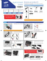
3. Disassembly and Reassembly

4. Troubleshooting

5. Exploded View & Part List

6. Wiring Diagram

LCD-TV

Chassis  :  N69A
Model 

:  LA32B650T1R


   LA40B650T1R


   LA46B650T1R


   LA55B650T1R 

 LA32B650T1R/LA40B650T1R/ 

LA46B650T1R/LA55B650T1R

Summary of Contents for LA32B650T1R

Page 1: ...ear cover for the more information 1 Precautions 2 Product specifications 3 Disassembly and Reassembly 4 Troubleshooting 5 Exploded View Part List 6 Wiring Diagram LCD TV Chassis N69A Model LA32B650T1R LA40B650T1R LA46B650T1R LA55B650T1R LA32B650T1R LA40B650T1R LA46B650T1R LA55B650T1R ...

Page 2: ...sassembly and Reassembly 3 1 3 1 Disassembly and Reassembly 3 1 4 Troubleshooting 4 1 4 1 Troubleshooting 4 1 4 2 Alignments and Adjustments 4 20 4 3 Factory Mode Adjustments 4 21 4 4 White Balance Calibration 4 26 4 5 White Ratio Balance Adjustment 4 28 4 6 Servicing Information 4 29 4 7 Sub Micom Update 4 41 5 Exploded View Part List 5 1 5 1 LA32B650T1R Exploded View 5 1 5 2 LA40B650T1R Exploded...

Page 3: ...urope samsungportal com China http china samsungportal com Asia http asia samsungportal com Mideast Africa http mea samsungportal com This Service Manual is a property of Samsung Electronics Co Ltd Any unauthorized use of Manual can be punished under applicable International and or domestic law 2009 Samsung Electronics Co Ltd All rights reserved Printed in Korea P N BN82 00552A 00 ...

Page 4: ...atically sensitive devices Use caution when handling these components 3 1 Disassembly and Reassembly Cautions 1 Disconnect the LCD TV from the power source before disassembly 2 Follow these directions carefully never use metal instruments to pry apart the cabinet Description Picture Description Screws 1 Place monitor face down on cushioned table Remove screws from the Stand Remove stand Screw size...

Page 5: ...3 2 3 Disassembly and Reassembly Description Picture Description Screws 2 Remove the screws of rear cover 3 Lift up and remove the rear cover Rear view of 32 40 Rear view of 46 55 ...

Page 6: ...embly and Reassembly Description Picture Description Screws 4 Remove the screws of main board 4 1 Remove the screws of IP board Remove the IP board 32 40 4 2 Remove the screws of IP board Remove the IP board 46 55 ...

Page 7: ...3 4 3 Disassembly and Reassembly Description Picture Description Screws 5 Remove the speakers R L 6 Remove the screws of Stand BKLT Lift up the Stand BKLT 7 Remove the screw of panel top ...

Page 8: ... Disassembly and Reassembly Description Picture Description Screws 7 1 Remove the screw of wall bracket 46 55 only 8 1 Front 8 2 Panel Reassembly procedures are in the reverse order of disassembly procedures ...

Page 9: ...5 1 5 Exploded View Part List 5 Exploded View Part List 5 1 LA32B650T1R Exploded View T0003 T0175 M0215 M0115 M0174 M0146 M0014 M0254 M0027 T0920 M0013 ...

Page 10: ... 2 1 S A T0175 BN96 09463A ASSY SPEAKER P 8ohm 4pin 10W R 200 L 4 1 S A M0254 BN61 04800E HOLDER SIDE AV SO LO ABS PMMA HB BK23 2U 1 S N A M0014 BN94 03117Z ASSY PCB MAIN LA32B650T1RXXT 1 S A M0146 BN61 04818A BRACKET PANEL TOP B650 32 SECC T1 2 2 S N A M0174 BN44 00261B IP BOARD H32F1_9DY H32F1_9DY 0 12mA 12 5 1 S A T0920 BN61 04812A GUIDE STAND 32 PET PC G F 15 V2 BK500 1 S A M0013 BN96 09502C A...

Page 11: ...mm WHITE 0 26 S N A 4 BN61 04842D HOLDER BOSS SIDE L 32 LB650 ABS PMMA HB 1 S N A 3 BN96 09517B ASSY HOLDER P BOSS BOTTOM 32 LB650 ABS H 1 S N A 4 BN61 04692A BOSS PRIMER 94 clear 35cps 0 3 S N A 4 BN61 04731B BOSS TAPE AMBER ACRYL T1 1 W12 0mm WHITE 0 52 S N A 4 BN61 04731D BOSS TAPE AMBER ACRYL T1 1 W20 0mm WHITE 0 06 S N A 4 BN61 04825B HOLDER BOSS BOTTOM 32 LB650 ABS HB WH12 1 S N A 3 M0125 BN...

Page 12: ...001480 CONNECTOR DSUB 15P 3R FEMAIL STAMPED PIN 1 S A 3 3711 003847 HEADER BOARD TO CABLE BOX 12P 1R 2mm ANG 1 S N A 3 3711 005884 HEADER BOARD TO BOARD BOX 30P 2R 2mm ANG 1 S A 3 3711 006715 HEADER BOARD TO CABLE BOX 4P 1R 2 5mm AN 1 S N A 3 JA330 3722 001061 JACK PHONE 1P 3 6PI AG BLK N 4 S A 3 3722 002426 JACK MODULAR 8P 8C N STRAIGHT GRN YEL AU 1 S A 3 AJACK4 3722 002546 JACK USB 4P 1C AU BLK ...

Page 13: ...ARISTOR 30Vdc 5A 1 6x0 8x0 8mm TP 23 S A 4 PR4 2007 000052 R CHIP 10Kohm 1 1 10W TP 1608 1 S A 4 KR24 2007 000067 R CHIP 15Kohm 1 1 10W TP 1608 1 S A 4 PR6 2007 000072 R CHIP 47ohm 5 1 10W TP 1608 4 S A 4 R105 2007 000138 R CHIP 100ohm 5 1 16W TP 1005 2 S A 4 AR49 2007 000140 R CHIP 1Kohm 5 1 16W TP 1005 3 S A 4 MR306 2007 000141 R CHIP 2 2Kohm 5 1 16W TP 1005 11 S A 4 AVR73 2007 000142 R CHIP 2 7...

Page 14: ...001590 R NETWORK 47Kohm 5 1 16W L CHIP V 4P TP 1 S N A 4 AC1 2203 000125 C CER CHIP 1 2nF 10 50V X7R TP 1608 4 S A 4 PC43 2203 000233 C CER CHIP 0 1nF 5 50V C0G TP 1005 9 S A 4 C134 2203 000257 C CER CHIP 10nF 10 50V X7R TP 1608 2 S A 4 RC34 2203 000280 C CER CHIP 0 01nF 0 5pF 50V C0G 1608 1 S A 4 DC2 2203 000330 C CER CHIP 012nF 5 50V C0G TP 1005 3 S A 4 C304 2203 000405 C CER CHIP 0 18nF 5 50V C...

Page 15: ...TER EMI SMD 5V 0 13A 0pF 2x1x0 5mm TP 2 S A 4 T0568 3301 001236 BEAD SMD 60ohm 1608 7 S N A 4 T0568 3301 001404 BEAD SMD 30ohm 2012 TP 15 9OHM 30MHz 32 S A 4 3701 001591 CONNECTOR HDMI 19P 2ROW FEMALE SMD S AU 3 S N A 4 3711 005925 HEADER BOARD TO CABLE BOX 51P 1R 0 5mm S 1 S N A 4 T0077 BN41 01156B PCB MAIN B650 Ready FR 4 4 1 0 1 2 192 1 1 S N A 4 BN97 03367A ASSY MICOM SUB T CHEAEUS 1005 2009 0...

Page 16: ... BH68 00329D LABEL BAR CODE 02 NO CE NO WT Y MPRII LA 2 S N A 2 BN69 03514X BOX SET 32LB650 CB A 01 DW3 AB YEL W88 1 S N A 0 1 M0045 BN92 05519H ASSY ACCESSORY LA32B650T1RXXL 1 S N A 2 BN96 10558N ASSY ACCESSORY MANUAL INDIA LB6T 1 S A 3 T0524 6902 000110 BAG PE LDPE T0 05 W250 L400 TRP 28 2 9 2 1 S N A 3 AA68 00487D MANUAL FLYER WARRANTY CARD comm ALL Engl 1 S N A 3 AA68 03242M MANUAL FLYER MANUA...

Page 17: ...5 1 5 Exploded View Part List 5 Exploded View Part List 5 1 LA32B650T1R Exploded View T0003 T0175 M0215 M0115 M0174 M0146 M0014 M0254 M0027 M0013 ...

Page 18: ...CKET STAND LINK B650 32 SECC T1 2 1 S A T0175 BN96 09463A ASSY SPEAKER P 8ohm 4pin 10W R 200 L 4 1 S A M0254 BN61 04800E HOLDER SIDE AV SO LO ABS PMMA HB BK23 2U 1 S N A M0014 BN94 03117Z ASSY PCB MAIN LA32B650T1RXXT 1 S A M0146 BN61 04818A BRACKET PANEL TOP B650 32 SECC T1 2 2 S N A M0174 BN44 00261B IP BOARD H32F1_9DY H32F1_9DY 0 12mA 12 5 1 S A M0013 BN96 09502G ASSY COVER P REAR 32LB650 TSE PC...

Page 19: ... LB650 ABS PMMA HB 1 S N A 3 BN96 09505D ASSY HOLDER P BOSS SIDE LEFT 32 LB650 PM 1 S N A 4 BN61 04692A BOSS PRIMER 94 clear 35cps 0 1 S N A 4 BN61 04731A BOSS TAPE AMBER ACRYL T1 1 W8 0mm WHITE 0 03 S N A 4 BN61 04731F BOSS TAPE AMBER ACRYL T1 1 W6 0mm WHITE 0 26 S N A 4 BN61 04842D HOLDER BOSS SIDE L 32 LB650 ABS PMMA HB 1 S N A 3 BN96 09517B ASSY HOLDER P BOSS BOTTOM 32 LB650 ABS H 1 S N A 4 BN...

Page 20: ...2 001463 SOLDER WIRE LFC2 W3 0 D3 99 79Sn 0 2Cu 1 219 S N A 3 0202 001608 SOLDER WIRE FLUX LFC7 107 D0 8 99 3Sn 0 0 25 S N A 3 0204 002420 SOLVENT 1M 1000 C3H70H 96 5 38 S N A 3 0204 002606 FLUX LF 715K 14 16kg Gravity 0 82 3 503 S N A 3 3701 001388 CONNECTOR HDMI 20P Phosphor Bronze ANGLE 1 S A 3 3701 001480 CONNECTOR DSUB 15P 3R FEMAIL STAMPED PIN 1 S A 3 HB01A 3711 003847 HEADER BOARD TO CABLE ...

Page 21: ...ER RTL8100CSL LF LQF 1 S N A 4 1205 003201 IC BUS SWITCH TC7WB125FK SSOP 8P 2x2 3mm 2 S A 4 1205 003352 IC CODEC WM8593SEFT V TQFP 64P 10x10mm P 1 S A 4 1205 003733 IC SWITCH AP2191MPG 13 MSOP 8L EP 8P 2 9 1 S A 4 1205 003735 IC SWITCH AP2151WG 7 SOT25 5P 2 9x1 6mm 1 S A 4 1209 001830 IC PLL IDT6V10012PGG TSSOP 20P 6 5x4 4mm 1 S A 4 1405 001185 VARISTOR 24Vdc 1 6x0 8x0 36mm TP 1 S A 4 1405 001233 ...

Page 22: ...HIP 750ohm 1 1 16W TP 1005 1 S A 4 DRP29 2011 000515 R NETWORK 4 7Kohm 5 1 16W L CHIP 8P TP 8 S A 4 DAR09 2011 001262 R NETWORK 22ohm 5 1 16W L CHIP 8P TP 2 32 S A 4 2011 001264 R NETWORK 10ohm 5 1 16W L CHIP 8P TP 2 8 S N A 4 HRP2 2011 001344 R NETWORK 100ohm 5 1 16W L CHIP 8P TP 2 2 S A 4 2011 001448 R NETWORK 10ohm 5 1 16W L 4P T 1010 1 S A 4 2011 001586 R NETWORK 1Kohm 5 1 16W L CHIP V 4P TP 1...

Page 23: ... 680uH 20 7070 1 S A 4 T0052 2703 003559 INDUCTOR SMD 4 7uH 20 8080 2 S N A 4 T0052 2704 000018 INDUCTOR SMD ARRAY 15uH 2000mA 2 0 124oh 2 S A 4 X202 2801 003326 CRYSTAL SMD 24MHZ 30PPM 28 ABX 20PF 50OH 1 S A 4 X202 2801 003773 CRYSTAL SMD 12MHz 30ppm 28 AAN 20pF 50oh 1 S A 4 X202 2801 004629 CRYSTAL SMD 27MHz 20ppm 12pF 50ohm TP 1 S N A 4 X202 2801 004734 CRYSTAL SMD 25 000000MHz 20ppm 28 AAN 12 ...

Page 24: ... W SS PET POLYESTER T0 05 1 S N A 0 1 BN92 05463E ASSY BOX 32 LB650 XL SIEL 1 S N A 2 AA02 00013A TAPE ETC RIBBON 101CM 250MT 0 1 S N A 2 T0077 BH68 00329D LABEL BAR CODE 02 NO CE NO WT Y MPRII LA 2 S N A 2 BN69 03514X BOX SET 32LB650 CB A 01 DW3 AB YEL W88 1 S N A 0 1 M0045 BN92 05519H ASSY ACCESSORY LA32B650T1RXXL 1 S N A 2 BN96 10558N ASSY ACCESSORY MANUAL INDIA LB6T 1 S A 3 0203 000367 TAPE CE...

Page 25: ... ANSI C101 1 Leakage Current for Appliances and Underwriters Laboratories UL Publication UL1410 59 7 With the unit completely reassembled plug the AC line cord directly into a 120V AC outlet With the unit s AC switch 4 first in the ON position and then OFF measure the current between a known earth ground metal water pipe conduit etc and all exposed metal parts including metal cabinets screwheads a...

Page 26: ... instrument s ground lead last 1 3 Electrostatically Sensitive Devices ESD Precautions Some semiconductor solid state devices can be easily damaged by static electricity Such components are commonly called Electrostatically Sensitive Devices ESD Examples of typical ESD are integrated circuits and some field effect transistors The following techniques will reduce the incidence of component damage c...

Page 27: ... it from being exposed 4 to moisture Otherwise it may cause a fire or electric shock Make sure to turn the power off and unplug the power cord from the outlet before repositioning the product Also check 5 the antenna cable or the external connectors if they are fully unplugged Damage to the cord may cause fire or electric shock Keep the antenna far away from any high voltage cables and install it ...

Page 28: ...1 4 1 Precautions Memo ...

Page 29: ... p 5 positive at 75Ω internally terminated Input Sync Signal H V Separate TTL P or N Maximum Pixel Clock rate 310Mhz Active Display Horizontal Vertical 698 4 H x 392 85 V mm AC power voltage Frequency AC 110V 220V 60 Hz Power Consumption 130 W 1W stand by Dimensions 802 9 x 239 0 x 601 0 mm_with stand 802 9 x 77 1 x 544 9 mm_without_stand Set W x D x H Weight Set 14 2kg_with stand 10 8kg_without s...

Page 30: ...ted Input Sync Signal H V Separate TTL P or N Maximum Pixel Clock rate 310Mhz Active Display Horizontal Vertical 885 6 H x 498 15 V mm AC power voltage Frequency AC 110V 220V 60 Hz Power Consumption 200 W 1W stand by Dimensions 995 1 x 255 0 x 705 9 mm with stand 995 1 x 78 6 x 650 4 mm without stand Set W x D x H Weight Set 41 23 lbs 18 7kg with stand 32 63 lbs 14 8kg without stand TV System Tuni...

Page 31: ...put Sync Signal H V Separate TTL P or N Maximum Pixel Clock rate 310Mhz Active Display Horizontal Vertical 1018 08 H x 572 67 V mm AC power voltage Frequency AC 110V 220V 60 Hz Power Consumption 230 W 1W stand by Dimensions 1126 1 x 277 0 x 783 4 mm with stand 1126 1 x 78 6 x 730 3 mm without stand Set W x D x H Weight Set 53 79 lbs 24 4kg with stand 42 77 lbs 19 4kg without stand TV System Tuning...

Page 32: ...ync Signal H V Separate TTL P or N Maximum Pixel Clock rate 310Mhz Active Display Horizontal Vertical 45 35 x 25 51 inches 1152 H x 648 V mm AC power voltage Frequency AC 110V 220V 60 Hz Power Consumption 310 W 1W stand by Dimensions 1310 8 x 308 0 x 894 8 mm with stand 1310 8 x 79 9 x 841 8 mm without stand Set W x D x H Weight Set 76 50 lbs 34 7kg with stand 64 81 lbs 29 4kg without stand TV Sys...

Page 33: ... V L V H V H V H UHF UHF UHF UHF UHF UHF UHF UHF UHF UHF UHF UHF UHF UHF UHF UHF UHF UHF UHF UHF UHF UHF UHF UHF UHF UHF UHF UHF UHF UHF UHF 49 75 59 25 77 25 85 25 93 25 175 25 183 25 191 25 199 25 207 25 215 25 223 25 45 75 53 75 61 75 95 75 201 25 471 25 479 25 487 25 495 25 503 25 511 25 519 25 527 25 535 25 543 25 551 25 559 25 567 25 575 25 583 25 591 25 599 25 607 25 615 25 623 25 631 25 63...

Page 34: ...F UHF UHF UHF UHF VHF VHF VHF 719 25 727 25 735 25 743 25 751 25 759 25 767 25 775 25 783 25 791 25 799 25 807 25 815 25 823 25 831 25 839 25 847 25 855 25 62 25 82 25 192 25 201 25 210 25 217 25 224 25 77 25 85 25 93 25 199 25 207 25 UHF UHF UHF UHF UHF UHF UHF UHF UHF UHF UHF UHF UHF UHF UHF UHF UHF UHF VHF V L V H V H V H VHF VHF V L V L VHF V H V H 719 25 727 25 735 25 743 25 751 25 759 25 767...

Page 35: ... 479 25 487 25 495 25 503 25 511 25 519 25 527 25 535 25 543 25 551 25 559 25 607 25 615 25 623 25 631 25 639 25 647 25 655 25 663 25 671 25 679 25 687 25 695 25 703 25 711 25 719 25 727 25 735 25 743 25 751 25 759 25 767 25 775 25 783 25 791 25 799 25 807 25 815 25 VHF V L V L V L V L VHF V H V H V H V H VHF VHF UHF UHF UHF UHF UHF UHF UHF UHF UHF UHF UHF UHF UHF UHF UHF UHF UHF UHF UHF UHF UHF U...

Page 36: ... 25 191 25 199 25 207 25 215 25 223 25 UHF UHF UHF UHF UHF UHF UHF UHF UHF UHF UHF UHF UHF UHF UHF UHF UHF UHF VHF V L V H V H V H VHF VHF VHF V L V L V L VHF VHF VHF 823 25 831 25 839 25 847 25 855 25 863 25 567 25 575 25 583 25 591 25 599 25 UHF UHF UHF UHF UHF UHF UHF UHF UHF UHF UHF 699 25 705 25 711 25 717 25 723 25 729 25 735 25 741 25 747 25 753 25 759 25 765 25 771 25 777 25 783 25 789 25 ...

Page 37: ...HF UHF UHF UHF UHF UHF UHF UHF 103 25 111 25 119 25 127 25 135 25 143 25 151 25 159 25 167 25 231 25 239 25 247 25 253 25 263 25 271 25 279 25 287 25 295 25 303 25 311 25 319 25 327 25 335 25 343 25 351 25 359 25 367 25 375 25 383 25 391 25 399 25 407 25 415 25 423 25 431 25 439 25 447 25 455 25 463 25 VHF VHF VHF VHF VHF VHF VHF VHF VHF VHF VHF VHF VHF VHF VHF VHF VHF VHF UHF UHF UHF UHF UHF UHF ...

Page 38: ... UHF UHF UHF UHF UHF 112 25 120 25 128 25 136 25 144 25 152 25 160 25 224 25 232 25 240 25 248 25 256 25 264 25 272 25 280 25 288 25 296 25 304 25 312 25 320 25 328 25 336 25 344 25 352 25 360 25 368 25 376 25 384 25 392 25 400 25 408 25 416 25 424 25 432 25 440 25 448 25 456 25 x x x x VHF VHF VHF VHF VHF VHF VHF VHF VHF VHF VHF VHF VHF VHF VHF VHF VHF UHF UHF UHF UHF UHF UHF UHF UHF UHF UHF UHF ...

Page 39: ...5 433 25 439 25 445 25 451 25 457 25 463 25 469 25 475 25 481 25 487 25 493 25 499 25 505 25 511 25 517 25 523 25 529 25 535 25 541 25 547 25 553 25 559 25 565 25 571 25 577 25 583 25 589 25 595 25 601 25 607 25 613 25 619 25 625 25 631 25 637 25 643 25 91 25 97 25 103 25 109 25 115 25 UHF UHF UHF UHF UHF UHF UHF UHF UHF UHF UHF UHF UHF UHF UHF UHF UHF UHF UHF UHF UHF UHF UHF UHF UHF UHF UHF UHF U...

Page 40: ...rsion Frames A and B appear every 1 50th of a second normally However the eye is sensitive to this frame rate which can result in the appearance of blurred images By interpolating frame A and inserting it in between frames A and B this motion blur artifact is virtually eliminated ...

Page 41: ...cellation Motion Judder cancellation for HD film image Adaptive Recursive Search ARS Implementation IPC MJC at same time Search Range Horizontal 72 Pixel Vertical 12 Line OFF ON Technology Example Block Diagram Video Signal Film Detection ME ARS IPC MJC Motion Judder Motion Judder Cancellation ...

Page 42: ... C In overlay mode while displaying the dock at least 3 4 of the video is free of graphical overlays D YahooTV is executed to overlay mode at first time 2 3 2 Viewport Mode Viewport Sidebar Mode Viewport Dock Mode Viewport Sidebar Mode Viewport Dock Mode Viewport Sidebar Mode Viewport Sidebar Mode Viewport Dock Mode Viewport Dock Mode A In viewport mode the video plays in a scaled down size coveri...

Page 43: ...the Internet Using the Content Library Menu Press the MENU button Press the or button to select Application then press the ENTER button Press the or button to select Content Library then press the ENTER button The Content Library main menu is displayed Press the or button to select an icon Gallery Cooking Game Children Wellness Other Content Management then press the ENTER button 1 2 3 Using the R...

Page 44: ...Publishing The copyrights of the Cooking contents and all issues related to them are reserved by Practical Pictures Game Check Mate Wise Star This category provides entertainment games for the whole family For the buttons used in the games refer to the directions on the screen Color Buttons for Games Button Operations Red Press to move to the game home screen Green Press to pause the game Yellow O...

Page 45: ...he game Take care as removing the USB memory device while saving data to the USB memory device may cause the data to be lost Downloading New Contents New content other than the built in contents will be provided via the Samsung com website with or without charge Downloading Content Visit the www samsung com website and open the Content Library page Enter the product number UDN Unique Device Number...

Page 46: ...h this TV Media Play only supports USB Mass Storage Class devices MSC MSC is a Mass Storage Class Bulk Only Transport device Examples of MSC are Thumb drives and Flash Card Readers Both USB HDD and HUB are not supported Please connect directly to the USB port of your TV If you are using a separate cable connection there may be a USB Compatibility problem Before connecting your device to the TV ple...

Page 47: ...80 H 264 MP 1920 x 1080 H 264 HP 1920 x 1080 MPEG 4 SP 800 x 600 MPEG 4 ASP 800 x 600 Motion JPEG 800 x 600 asf ASF Divx 3 11 800 x 600 WMA MP3 AC3 LPCM ADPCM MULAW ALAW AAC Divx 4 x 800 x 600 Divx 5 1 800 x 600 Divx 6 0 1920 x 1080 XviD 1920 x 1080 H 264 BP 1920 x 1080 H 264 MP 1920 x 1080 H 264 HP 1920 x 1080 MPEG 4 SP 800 x 600 MPEG 4 ASP 800 x 600 wmv VC1 Window Media Video v9 1920 x 1080 mp4 ...

Page 48: ...ved O O O O Video Only O X Index damaged file O X X O X X AVI 2 0 Interleaved O O O O O X Non Interleaved O X X O Video Only X X Index damaged file O X X O X X MP4 Interleaved O O O O O X Non Interleaved O O O O Support a part O X Index is ahead O O O O O X Index is at the back O O O O O X PS O O O O O X TS O O O O O X 3gp Interleaved O O O O O X Non Interleaved O O O O Support a part O X Index is...

Page 49: ...B devices Connection TV PC connection Same as DLNA network setting Using Ad hoc TV Mobile phone connection Connect wireless usb dongle to TV Select Wireless in Setup Network Type menu Move to Setup Wireless Network Setup menu Select between Auto and Manual In case of Manual setting input value of IP Address Subnet Mask Gateway and DNS Server manually At this time IP Address of TV and wireless netw...

Page 50: ...2 22 2 Product specifications Message Media Message arrived Media arrived Phone call Preparing to play Scheduled event Playing Media ...

Page 51: ...x D 995 1 x 705 9 x 255 0 mm with stand 995 1 x 650 4 x 78 6 mm without stand 998 0 x 704 0 x 300 0 mm with stand 998 0 x 638 0 x 83 3 mm without stand Weight 41 23 lbs set 64 81 lbs package 44 53 lbs set 58 20 lbs package Brightness 500 nit 500 nit Contrast Ratio 50000 1 50000 1 Picture Enhacer DNIe FBE3 DNIe FBE3 Equalizer 5 Band 5 Band Auto Motion Plus 120Hz O O Surround Sound 2 Way SRS TruSurr...

Page 52: ...emark Remote Control Batteries AAA x 2 BN59 00873A Samsung Electronics Service center Power Cord 3903 000145 Cover Bottom LA32B650T1R BN63 05284B LA40B650T1R BN63 05286B LA46B650T1R BN63 05287B LA55B650T1R BN63 05478B Owner s Instructions BN68 00774D Cleaning Cloth BN63 01798B ...

Page 53: ...nversion Board Check internal Pattern both of FRC and FBE3 if there is some picture noise FRC Factory mode Info MENU MUTE power on Advanced Menu Option Block FRCM TP After DDR Press right button of Remocon FBE3 Factory mode Info MENU MUTE power on_ Advanced Menu Option Block FBE3 Patt Sel Press right button of Remocon Case1 FBE3 ok FRC NG change the FRC Board Case2 FBE3 NG change the main Board Ch...

Page 54: ...le connected to Main Board If necessary replace the Main Board Check the Power Cord Yes No No Is standby LED on Yes A5V appear at the pin 27 of CN201 Yes is any sound of TV Yes Check dimming cable If necesary replace the Main Board Yes Check 30p cable If necessary replace the IP board Yes B13V appear at the pin 9 or 10 of CN201 Yes Change the main board Please contact Tech support ...

Page 55: ...K Supported frequencies are 8 11 025 12 16 22 05 24 32 44 1 48 Khz I cannot play MP3 files downloaded from websites Paid MP3 download sites such as Melon An explanation of WISELINK Playing DRM files used to protect content is not supported I want to know about supported USB devices An explanation of WISELINK The TV only supports devices that do not support the Mass Storage Class or PTP Class Devic...

Page 56: ...er sharing the folder including the file If you are unsure about this please click the button again and recheck if the file is displayed after a while I can see the folders shared through the PC Share Manager but I cannot see the files Content Sharing Since it shows only files corresponding to the Image Music and Movie categories files that do not correspond to these categories may not be displaye...

Page 57: ... playing speed normal After that you will be able to use the Seek function Although I can play some files I cannot play others even if they have the same resolution and format DLNA Video Play For unsupported videos some videos at a certain resolution and format may be played I can run Trick and Seek with a USB device but I cannot run Trick and Seek with DLNA DLNA Video Play For DNLA Trick is not s...

Page 58: ...ke care to not press the Ch Up Down Ch List Guide Pre Ch and Fav Ch buttons by mistake I have heard that the default built in content is played by the Adobe flash player Therefore I have downloaded Flash content from the Internet and tried to play it from the USB memory device but it does not play What is the problem The Contents Library does not support playing files other than the files authoriz...

Page 59: ...r at R242 Change the Main Assy No Does proper DC B3 3V B9V CORE_1 2V CLS_1 8V appear at C240 R207 C263 No Lamp Backlight Off power indicator LED on Yes No Check a connetion power code Check the backlight on when 30p cable unconnected No Change 30p cable 32 BN39 01099H 40 46 55 BN39 01099K or Change Main Power Assy 32 BN44 00261B 40 BN44 00264C 46 BN44 00265B 55 BN44 00268A Yes Does proper Main DC ...

Page 60: ...digital data appear at R1030F FRC_M_HSYNC Pin 19 20 34 35 LVDS Data clk of LVDS connector Power indicator LED is off Lamp Backlight on no video No Check the PC source and check the connection of D SUB Does the signal appear at C464 C465 C466 R1250 BD1205 R G B H V of IC501 No No Please Contact Tech support Check the LVDS cable Replace the LCD panel Check IC601 Change the Main Assy Yes Yes Yes Inpu...

Page 61: ...4 9 4 Troubleshooting WAVEFORMS 1 PC input V sink H sink R G B 2 LVDS output ...

Page 62: ...r Indicator is off Lamp Backlight Off no video Yes Check the HDMI source and check the connection of HDMI cable No Input the HDMI signal properly Yes Check IC1401 HDMI switch Change the Main Assy Yes Check the LVDS cable Replace the LCD panel Please Contact Tech support No Does the signal appear at D1423H Pin 10 6 HDMI1 D1425H Pin 10 6 HDMI2 D1427H Pin 10 6 HDMI3 D1421H Pin 10 6 HDMI4 HDMI RX_Clk ...

Page 63: ...4 11 4 Troubleshooting WAVEFORMS 3 PC input V sink H sink R G B 2 LVDS output ...

Page 64: ... Power indicator LED is off Lamp Backlight on no video Yes Check the RF source and check the connection of RF cable No Input the RF source properly Yes Check Tuner Change the Main Assy Yes Check the LVDS cable Replace the LCD panel Please Contact Tech support No Does the DC B33V_Tuner B5V_Tuner appear at 4 2 Pin of Tuner Does the digital data appear at R1030F FRC_M_HSYNC Pin 19 20 34 35 LVDS Data ...

Page 65: ...4 13 4 Troubleshooting WAVEFORMS 4 CVBS OUT Grey Bar 2 LVDS output ...

Page 66: ...Power indicator LED is off Lamp Backlight on no video Yes Check the video source and check the connection of video cable No Input the video source properly Yes Yes Check the LVDS cable Replace the LCD panel Please Contact Tech support No Does the CVBS data appear at C443 AV1 C441 AV2 Does the digital data appear at R1030F FRC_M_HSYNC Pin 19 20 34 35 LVDS Data clk of LVDS connector No Check IC601 C...

Page 67: ...4 15 4 Troubleshooting WAVEFORMS 4 CVBS OUT Grey Bar 2 LVDS output ...

Page 68: ... Pb Pr No Yes Power indicator LED is off Lamp Backlight on no video Yes Check the component source and check the connection of component cables Y Pb Pr No Input the component source properly Yes Check CN1301 or CN1203 Change the Main Assy Yes Check the LVDS cable Replace the LCD panel Please Contact Tech support No Does the digital data appear at R1030F FRC_M_HSYNC Pin 19 20 34 35 LVDS Data clk of...

Page 69: ...4 17 4 Troubleshooting WAVEFORMS 5 Compnent_Y Gray scale Pb Pr Color bar 2 LVDS output ...

Page 70: ...connection of sound cable Comp PC DVI to HDMI Yes Change the Main Assy Yes Does the sound data appear at C1521 C1522 AV2 R L C1523 C1524 Comp1 AV1 R L C1519 C1520 Comp2 R L C1527 C1528 DVI R L C1529 C1530 PC R L Does the I2C data appear at R1501 R1502 No Check IC1501 Audio CODEC Change the Main Assy No Input the sound source properly Yes Replace speaker Please Contact Tech support No Does the soun...

Page 71: ...4 19 4 Troubleshooting WAVEFORMS 6 I2C Data 7 Speaker out ...

Page 72: ...s essential Avoid overload Excessive signal from a sweep generator might overload the front end of the TV When inserting signal markers do not allow the marker generator to distort test result Connect the TV only to an AC power source with voltage and frequency as specified on the backcover nameplate Do not attempt to connect or disconnect any wire while the TV is turned on Make sure that the powe...

Page 73: ...SmL4M 58FMfK1M 63FMmK1M 50FMfU4M Model LB550 LB570 UB6000 LB650 LB670 UB7000 LB750 UB8000 PB550 PB560 PB570 PB610 PB650 PB670 PB750 TUNER ALPS SEC_T SEC_TC SEC_TS SEC_TCS Region PANEURO PANNORDIG ASIA_DTV ASIA_ATV DDR Light Effect ON OFF Ch Table 0 Info Link Type America Mexico S America Infolink ON Infolink OFF Country 0 Local SET Vietnam Philippines China India Iran Israel Middle Asia East Asia ...

Page 74: ...m View Log Font Data Viewer 600ms 0ms 1000ms OFF ON Debug Uart ON OFF 255 ON OFF 2 0 14 2 0 8 4 0 15 OFF 0 85 0 88 0 90 0 93 0 95 0 98 M1 M2 M3 M4 2Hr INT EXT PDP JEIDA VESA CHINA IRAN ISRAEL ARAB RED BLUE 5 0 9999 0 1 With DB WithOut DB ON OFF ON OFF ON OFF Not Support Cable Cable Wireless OFF ON OFF ON US_KR EU ASIA_SA CUSTOM 256 0 256 0 0 3 0 0 3 OFF ON Operating Development Flof List WestEurop...

Page 75: ...ption Name Range Asia Initial HOTEL MODE POWER ON CHANNEL POWER ON VOLUME MIN VOLUME MAX VOLUME PANEL BUTTON LOCK POWER ON SOURCE ON OFF 0 99 0 100 0 100 0 100 Lock UNLock ATV DTV PC1 SCART1 SCART2 5 Shop Option Name Range Asia Initial Shop Mode USB DEMO ON SEC USB DEMO OFF SEC Exhibition Mode OFF ON OFF ON OFF ON OFF ON OFF OFF OFF OFF 6 Asia Option Name Range Asia Initial TTX China HD NT Convers...

Page 76: ...CarrMute Low Thld DRC H Thresh DRC L Thresh DRC SW Thresh Chattering Cnt FM Prescale NICAM Prescale BTSC Mono Prescale BTSC Stereo Prescale BTSC Sap Prescale A2K Prescale M Prescale 0x20h 0x0h 0xffh 0x10h 0x0h 0xffh 100 0 150 100 0 150 0 0 150 40 0 150 40 0 150 0 0 150 40 0 150 127 0 127 ON OFF 1 2 0x30h 0x0h 0xffh 0x20h 0x0h 0xffh 0x70h 0x0h 0xffh 0x20h 0x0h 0xffh 0xah 0x0h 0xffh 0x5h 0x0h 0xffh ...

Page 77: ...HDMI FLT CNT SIG HDMI FLT CNT LOS UNSTABLE BAN CNT HDMI Err Cnt HDMI ROBIN HDMI Callback HDMI CTS Thld HDMI CTS CNT1 TMDS_EQ2_Boost TMDS_EQ2_Gain TMDS_PLL_Loop TMDS_CPREG_BLEED HDMI EQ 1 1 2 0 0 1 2 0 3 0 0 3 2 0 3 4 0 4 1 0 1 0 0 1 0 0 1 0 1 0 1 6 0 8 2 0 2 50 62 5 LCD PDP 3 0 4 OFF ON OFF ON OFF ON 1 1 2 40 0 100 Auto DVI Disable Enable 0mS 0 2000mS 300mS 0 1000mS 300mS 0 1000mS 2500mS 0 10000mS...

Page 78: ...attern 24 Chess Pattern Chess Pattern 4 Use Equipment CA210 Master MSPG925 Generator Use other equipment only after comparing the result with that of the Master equipment Input mode Calibration Pattern CVBS IN Model_ 1 Perform in NTSC B W Pattern 24 Lattice Component IN Model_ 6 Perform in 720p B W Pattern 24 Lattice PC Analog IN Model_ 21 Perform in VESA XGA 1024x768 B W Pattern 24 Lattice HDMI I...

Page 79: ...te it returns to the high level menu 9 You can see the change of the DTV Calibration status from Failure to Success Method of Color Calibration PC 1 Apply the VESA XGA Lattice N0 21 pattern signal to the PC IN port 2 Press the Source key to switch to PC mode 3 Enter Service mode 4 Select 2 WB Adjust menu 5 Select the Calibration menu 6 Select the PC Calibration menu 7 In PC Calibration Failure sta...

Page 80: ...al values for each mode are configured by default Refer to Table 1 2 It varies with Panel s size and Specification 1 2 3 Equipment CA 210 Pattern MIK K 7256 92 Flat W B Pattern as standard Use other equipment only after comparing the result with that of the Master equipment Set Aging time 60min Calibration and Manual setting for WB adjustment HDMI Calibration at 24 Chessboard Pattern Manual adjust...

Page 81: ...ght 5 Luminance High light 0 1Ft L Low light 0 1Ft L 4 6 Servicing Information 4 6 1 USB Download Method Samsung may offer upgrades for TV s firmware in the future Please contact the Samsung call center at 1 800 SAMSUNG 7267864 to receive information about downloading upgrades and using a USB drive Upgrades will be possible by connecting a USB drive to the USB port located on located on the back o...

Page 82: ...ds Please be careful to not disconnect the power or remove the USB drive while upgrade is being applied The message Upgrade version XXXX to version XXXX The system would be reset after upgrade Press the left right button to select OK The TV will shut off after completing the firmware upgrade Please check the firmware version after the upgrade is complete ...

Page 83: ...4 31 4 Troubleshooting 3 How to check Program Version 1 To enter Factory mode 2 Check the micom version T CHEAEAC 00xxxx ...

Page 84: ...d JIG 1 Connect Power Uart cable to board and Turn on the board 2 Press shift to enter uboot prompt 3 Press any key to enter BOOTROM DEBUG SESSION before timeout 4 Make sure watchdog off If watchdog status is on then board will reboot after 15secs ...

Page 85: ...4 33 4 Troubleshooting 5 Press 0 6 Save latest BSP images to update folder in usb memory ...

Page 86: ...4 34 4 Troubleshooting 7 Enter bbm usb after connecting usb memory 8 Press 1 ...

Page 87: ...4 35 4 Troubleshooting 9 Enter u boot bin 10 Press x to return prompt menu ...

Page 88: ...4 36 4 Troubleshooting 11 Press shift to enter uboot prompt again 12 Press any key to enter BOOTROM DEBUG SESSION before timeout ...

Page 89: ...4 37 4 Troubleshooting 13 Press 0 14 Enter bbm usb If there is not a option Image is old version or not updated Then try again from No 1 ...

Page 90: ...4 38 4 Troubleshooting 15 Enter a 16 Enter directory path if update is right just input Enter key It takes about 1 minute ...

Page 91: ...4 39 4 Troubleshooting 17 Press x 18 Enter bbm show partition Check partition status same as red box on picture below If different go back to first phase Do it all again ...

Page 92: ... dtv mtd_boot mtd_epg mtd_swu usr etc mtd_chmap mtd_exe mtd_tlib lib mtd_cmmlib mtd_factory mtd_wiselink start_usb sh cd dtv ls usb cd usb ls log sda cd sda ls Autorun inf T CHL7DEUC update T CHL5DEUC photos zip exe cd update ls Image exe img oneboot bin uboot_env bin Image_serial fnw bin rootfs img validinfo txt appdata img info txt serial_temp version_info txt boot img onboot bin u boot bin 21 W...

Page 93: ...n not be operated by Remote Control Update sub micom Manufacture WELTREND Device Type WT61P8 Communication type D SUB15 Analog 1 1 Connect Sub Micom Download JIG DDC manager and D SUB JACK 1 2 Click Load File Choose to update Sub Micom file For example TP8_TT_EU_0015_N hex ...

Page 94: ...ooting 1 3 Click Auto Program to update Sub Micom S W 1 4 If Programming and Verifying are OK S W Updating is complete 1 5 Remove Download JIG Cable Turn off AC Power off the Set waiting a few seconds and turn on again ...

Page 95: ...6 1 6 Wiring Diagram 6 Wiring Diagram 6 1 Wiring Diagram 32 40 IP Board Main Board Speaker Speaker Speaker Speaker CN201 CN1002 CN1601 CN801 Function IR FRCQ T CON CN1501 ...

Page 96: ... Wiring Diagram 6 2 Wiring Diagram 46 55 Main Board Speaker Speaker Speaker Speaker CN201 CN1002 CN1601 CN801 Function IR FRCQ T CON CN1501 Panel CN1 Panel CN2 Panel CN3 CN1806 CN1808 CN1809 IP Board Driver ...

Page 97: ... 12 GND HDMI1_RX2 HDMI2_RX1 15 GND HDMI2_RX1 HDMI2_RX0 18 GND HDMI2_RX0 HDMI2_RXCLK GND CN1204 PC sound 1 2 3 4 5 6 7 GND PC_SR_IN PC_SL_IN PC_SL_IN PC_SL_IN PC_SR_IN PC_SR_IN CN1501 sound out 1 2 3 4 R R L L CN1201 Optical 1 2 3 VIN VCC GND CN903 USB1 1 2 3 4 USB1 VCC USBN 2 0 USBP 2 0 GND CN201 to Power board 1 2 3 4 5 6 7 8 9 10 11 12 13 14 15 H SYNC Power On Off GND 5 2V ST BY 5 2V GND GND 14V...

Page 98: ...NS TX TRANS RX B DGND B DGND TRANS RX B DGND B DGND B3 3V LED0_TXRX B3 3V LED1_LINK CN1301 Universal jack 1 2 3 4 5 6 7 8 9 10 11 12 13 14 COMP1_SR_IN GND COMP2 COMP1_SL_IN COMP1_SR_IN COMP2_PR COMP1_PR COMP2_PB COMP1_PB COMP_IDENT COMP2_Y COMP1_Y VIDEO1_IDENT COMP2_SR_IN 15 16 17 18 19 20 21 22 23 24 25 26 27 MONITOR_R_OUT COMP2_SR_IN MONITOR_L_OUT DVI_SR_IN GND COMP2_IDENT DVI_SL_IN DVI_SR_IN GN...

Page 99: ...Supply power from IP board to Driver Board left CN1809 Panel CN2 Supply power from IP board to Driver Board right 6 4 Cables Use Main IP 30P Main TCON IP BalanceBD 7P Code 32 BN39 01099K 600mm 40 46 55 BN39 01099B 800mm 32 BN96 10077A 250mm 40 BN96 10076A 300mm 46 BN96 10075A 350mm 55 BN96 10074A 450mm 46 55 BN39 00830B 200mm Photo Use IP BalanceBD L 2P IP BalanceBD R 2P Code 46 BN39 01021C 1100mm...

Reviews: