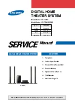
background image

SERVICE 

Manual

DIGITAL HOME THEATER SYSTEM

Refer to the service manual in the GSPN (see the rear cover) for the more information.

CONTENTS

1.  Precaution

2.  Product Specification

3.  Disassembly & Reassembly

4.  Troubleshooting

5.  Exploded View & Part List

6.  PCB Diagram

7.  Schematic Diagram

DIGITAL HOME 

THEATER SYSTEM

Model Name : HT-TZ315
Model Code : HT-TZ315R/EDC 

Speaker

HT-TZ315

Front

PS-FTZ315

Center

PS-CTZ315

Rear

PS-RTZ315

Subwoofer

PS-WTZ315

HT-TZ315

Summary of Contents for HT-TZ315

Page 1: ...mation CONTENTS 1 Precaution 2 Product Specification 3 Disassembly Reassembly 4 Troubleshooting 5 Exploded View Part List 6 PCB Diagram 7 Schematic Diagram DIGITAL HOME THEATER SYSTEM Model Name HT TZ315 Model Code HT TZ315R EDC Speaker HT TZ315 Front PS FTZ315 Center PS CTZ315 Rear PS RTZ315 Subwoofer PS WTZ315 HT TZ315 ...

Page 2: ...r domestic law GSPN Global Service Partner Network Area Web Site North America service samsungportal com Latin America latin samsungportal com CIS cis samsungportal com Europe europe samsungportal com China china samsungportal com Asia asia samsungportal com Mideast Africa mea samsungportal com Samsung Electronics Co Ltd Mar 2008 Printed in Korea ...

Page 3: ...sembly 3 1 4 Troubleshooting 4 1 Checkpoints by Error Mode 4 2 4 2 Measures to be taken when the Protection Circuit operates 4 25 4 3 Initialization Upgrade Methods 4 27 5 Exploded View Part List 5 1 Exploded View 5 2 5 2 Speaker System 5 4 5 3 Electrical Part List 5 5 6 PCB Diagram 6 1 Wiring Diagram 6 2 6 2 FRONT PCB Top 6 3 6 3 FRONT PCB Bottom 6 5 6 4 AMP PCB Top 6 6 6 5 AMP PCB Bottom 6 8 6 6...

Page 4: ...Contents 7 Schematic Diagram 7 1 Overall Block Diagram 7 2 7 2 FRONT 7 3 7 3 BLUETOOTH 7 4 7 4 AMP 7 5 7 5 MAIN 7 6 7 6 MICOM 7 7 7 7 ANALOG 7 8 7 8 HDMI 7 9 7 9 SMPS 7 10 ...

Page 5: ...e Current for Appliances and Underwriters Laboratories UL Publication UL1410 59 7 With the unit completely reassembled plug the AC line cord directly into a 120V AC outlet With the unit s AC switch first in the ON position and then OFF measure the current between a known earth ground metal water pipe etc and all exposed metal parts Examples Handle brackets metal cabinets screwheads and control sha...

Page 6: ... AC power cord for damage Make sure that no wires or components touch thermally hot parts 9 Product Safety Notice Some electrical and mechanical parts have special safety related characteristics which might not be obvious from visual inspection These safety features and the protection they give might be lost if the replacement component differs from the original even if the replacement is rated fo...

Page 7: ... been damaged 5 Check the insulation between the blades of the AC plug and accessible conductive parts examples metal panels input terminals and earphone jacks 6 Insulation Checking Procedure Disconnect the power cord from the AC source and turn the power switch ON Connect an insulation resistance meter 500V to the blades of the AC plug The insulation resistance between each blade of the AC plug a...

Page 8: ...cumulation of electrostatic charge 4 Do not use freon propelled chemicals These can generate electrical charges that damage ESDs 5 Use only a grounded tip soldering iron when soldering or unsoldering ESDs 6 Use only an anti static solder removal device Many solder removal devices are not rated as anti static these can accumulate sufficient electrical charge to damage ESDs 7 Do not remove a replace...

Page 9: ...ker Z310 Asia Bluetooth Connection The United States Bluetooth exclusion Communicate with B T mp3 or C phone Easy Convenient access Applies on Z310 Series only 1080P up scale support Near Full HD quality through all HDMI cable Including HDMI CEC HDMI Usage Expansion Applied on Z210 and Z310 series Improved Sound Quality Power Bass MXF Mutual Cross Function Enhanced Bass power Shield Sound Powered ...

Page 10: ...r Disc 135 min CD 12 cm COMPACT DISC Reading Speed 4 8 5 6 m sec Maximum Play Time 74 min CD 8cm COMPACT DISC Reading Speed 4 8 5 6 m sec Maximum Play Time 20 min Video Output Composite Video 576i 480i 1 channel 1 0 Vp p 75 Ω load Component Video 576i 480i Y 1 0 Vp p 75 load Pr 0 70 Vp p 75 Ω load Pb 0 70 Vp p 75 Ω load Video Audio HDMI 1080p 1080i 720p 576p 480p Amplifier Front speaker output 166...

Page 11: ...r Impedance 3Ω 3Ω Frequency range 140Hz 20KHz 45Hz 160Hz Output sound pressure level 86dB W M 88dB W M Rated input 166W 170W Maximum input 332W 340W Dimensions W x H x D Front Rear 90 x 1020 x 92 mm stand base 280 x 280 Center 300 x 101 x 91 5 mm Subwoofer 180 x 320 x 380 mm Weights Front 3 0 kg Center 0 9 kg Rear 3 0 kg Subwoofer 4 5 kg ...

Page 12: ...U DVD DVD R DVD RW MP3 JPEG Viewer DVD Audio except CIS except CIS DVD OK 4000 Songs only CIS 4000 Songs only CIS WMA DIVX AVI Divx3 11 Divx5 1 XviD WMV V1 V2 V3 V7 SACD X X WIRELESS Wireless Ready USB HOST Anynet Anynet Anynet DVD Video Progressive Scan NT PAL USA only NTSC USA only NTSC Logo copy NTSC PAL USA only NTSC CIS only PAL USA only NTSC CIS only PAL PAL M Brazil X X Sound Mode EQ DSP 3M...

Page 13: ...X2 Multi ch Out X X Out X X Optical jack In Digital In 1 2 Out X X Coaxial jack In X X Out X X i Link X X Headphone MIC Jack Headphone Jack 3 5Φ 1 X 2 MIC Jack 6 5Φ Wireless MIC CIS Only Tuner FM RDS X EU Only AM X X Preset Memory 15 15 Remote Key Universal MBR Key 57 Key 60 Key Dual Voltage HIGH LOW DUAL Voltage HIGH LOW DUAL Voltage Speaker Type Sat Tallboy Tallboy Tallboy Stand Impedance Sat Wo...

Page 14: ...s 2 4 1 Supplied Accessories Accessories Item Item code Remark Remote Control Batteries AH59 01907C 4301 000116 Samsung Service center Video Cable AH39 40001V FM Antenna AH42 00021A Owner s Instructions AH68 02055F AH68 02055G AH68 02055H Cloth Clean AH81 02286C ...

Page 15: ...ty instructions before performing any work as the IC chips on the PCB are vulnerable to static electricity Assemble in the reverse order of disassembly No Part Name Description Description Photo 1 COVER TOP 1 Unscrew the 2 screws from the Left and Right Side TAP TITE SCREW BH 3 10 BLACK 2 Unscrew the 3 screws from the Rear TAP TITE SCREW BH 3 10 BLACK 3 Lift the Top Cover to separate it Be careful...

Page 16: ...VER 3 CABINET FRONT 1 Remove the wires connected to the cabinet front In case of pulling up the PCB cable it is easier to pull up when pressing the grip 2 Lift and pull out the cabinet front 4 PCB 1 Remove the wires between PCBs In case of pulling up the PCB cable it is easier to pull up when pressing the grip 2 Remove the 8 screws on the PCBs TAP TITE SCREW BH 3 6 SILVER ...

Page 17: ...tronics 3 3 Disassembly Reassembly No Part Name Description Description Photo 5 CABINET BOTTOM REAR 1 Remove the remaining 5 screws in the rear TAP TITE SCREW BH 3 10 BLACK 6 Set 1 Picture of a disassembled product ...

Page 18: ...3 4 Samsung Electronics MEMO ...

Page 19: ...Samsung Electronics 4 1 Troubleshooting 4 Troubleshooting 4 1 Checkpoints by Error Mode 4 2 4 2 Measures to be taken when the Protection Circuit operates 4 25 4 3 Initialization Upgrade Methods 4 27 ...

Page 20: ...K 5V Check NORMAL VOLTAGE at SMPS PCB D51 Replace CON3 wire Check pattern from MCON2 to pin 22 of UIC1 Check for circuit at SMPS PCB ICM01 Fuse F1 D81 T1 T2 Replace D51 Check Resistance from GND to pin 22 of MICOM UIC1 If short 0 ohm Replace MICOM UIC1 No No Yes No Yes No The power does not turn on When POWER ON for Front PCB Check for HIGH voltage 5V at UIC2 pin 13 43 Replace the VFD DRIVER IC ZI...

Page 21: ...Samsung Electronics 4 3 Troubleshooting Check for connector from Main PCB to Front PCB ZCON1 Yes Check for Circuit at SMPS PCB D1 No Check for VFD 1 2 61 62 VFD DC 5V A ...

Page 22: ... 5 14 30 Check if the 3 3V of VDD is measured at the pin of 36 46 Replace the AIC1 IC Check the audio input of each component including connector connectivity Check if the pin 10 and 11 of CON3 of SMPS is 3 3V Check if the pin 12 13 of CON3 is 5V No No No No Sound Yes Yes B Check the outputs of the pin 4 7 9 of BPIC1 74LCX157 to check IPOD BT Check the VD33 is measured at the pin 1 16 of BPIC1 Rep...

Page 23: ...tput and connector connectivity B C Yes Refer to wave pattern image of Fig 4 4 1 and Fig 4 4 2 Check if the outputs of the pin 48 49 51 52 54 55 58 59 61 62 67 68 70 71 74 75 of MIC1 PS9829B of the AMP PCB are measured Check if the VDD 3 3V of MIC1 is measured at the pin of 4 10 22 29 Replace the MIC1 Check if the pin 22 of J7 is 3 3V No No Yes Check the PWM output Refer to wave pattern image of F...

Page 24: ...ured Replace the TAS5352 Check if the GVDD of pin 1 of J3 is 12V Check if the PVDD of pin 7 8 9 of J3 are 34 5V No Yes Check if GVDD of TAS5352 is measured at the pin 1 22 23 Check if PVDD of TAS5352 is measured at the pin 26 27 32 35 40 41 Yes No Check if the outputs of the SPK1 of AMP PCB are measured Refer to wave pattern image of Fig 4 5 Refer to wave pattern image of Fig 4 4 1 and Fig 4 4 2 ...

Page 25: ...Samsung Electronics 4 7 Troubleshooting ANALOG Page 7 8 IC31 AIC1 CEIC2 C1 MCON15 CN03 CJ1 MCON1 JK7 MAIN PCB Top Page 6 10 Fig 4 1 4 1 1 2 3 4 3 5 2 4 2 5 1 1 5 3 ...

Page 26: ...4 8 Samsung Electronics Troubleshooting MAIN Page 7 6 RIC4 BPIC1 MAIN PCB Top Page 6 10 Fig 4 2 6 6 6 6 ...

Page 27: ...amsung Electronics 4 9 Troubleshooting MICOM Page 7 7 MIC1 VI IC31 AIC1 CEIC2 CEIC1 BIC6 BIC5 MIC10 MIC3 MCON12 MCON15 CN03 CN10 CECJ1 MCON1 JK7 VJ4 MAIN PCB Top Page 6 10 Fig 4 3 7 7 7 8 9 9 0 0 8 0 9 8 ...

Page 28: ...4 10 Samsung Electronics Troubleshooting AMP Page 7 5 Fig 4 4 1 ...

Page 29: ...Samsung Electronics 4 11 Troubleshooting J7 FJ1 J3 MIC1 IC1L IC1CW IC1R NIC1 SIC1 AMP PCB Top Page 6 6 Fig 4 4 2 ...

Page 30: ...4 12 Samsung Electronics Troubleshooting AMP Page 7 5 IC1L CW SIC1 AMP PCB Top Page 6 6 Fig 4 5 ...

Page 31: ... 62 77 of MIC1 Check if VDD of 5V is measured at the pin 1 24 34 of VIC1 Replace the MIC1 IC Replace the VIC1 Check if the pin 10 11 of MCON2 are 3 3V Check if the pin 3 of CON3 is 5V No Yes No No COMPOSIT VIDEO OUT Yes Yes No Check the JP6 connectivity and replace it if necessary Check MPEG Output Check Video Switch Check JACK Output Check if composite video output is measured at the JP6 Refer to...

Page 32: ...4 14 Samsung Electronics Troubleshooting MAIN Page 7 6 1 MIC1 MIC2 RIC4 BPIC1 RIC3 CEIC2 BIC5 MIC6 MIC10 MIC3 MIC5 MCON8 CN03 CN10 CECJ1 MCON1 MAIN PCB Top Page 6 10 Fig 4 6 1 1 1 ...

Page 33: ...Samsung Electronics 4 15 Troubleshooting ANALOG Page 7 8 VIC1 IC31 AIC1 8 CN03 JK7 VJ4 MAIN PCB Top Page 6 10 Fig 4 7 2 2 2 ...

Page 34: ...1 Check if VDD of 5V is measured at the pin 1 of VIC1 Replace the MIC1 IC Replace the VIC1 Check if the pin 10 11 of MCON2 are 3 3V Check if the pin 12 13 of MCON2 is 5V No Yes No No COMPONENT Y Pb Pr Yes Yes No COMPONENT Y Pb Pr Check MPEG Output Check Video Switch Check JACK Output Check the VJ4 connectivity and replace it if necessary Check if composite video output is measured at the VJ4 Refer...

Page 35: ...Samsung Electronics 4 17 Troubleshooting MAIN Page 7 6 1 MIC1 MIC2 RIC4 BPIC1 RIC3 CEIC2 BIC5 MIC6 MIC10 MIC3 MIC5 MCON8 CN03 CN10 CECJ1 MCON1 MAIN PCB Top Page 6 10 Fig 4 8 1 3 3 2 3 2 1 2 1 ...

Page 36: ...4 18 Samsung Electronics Troubleshooting ANALOG Page 7 8 VIC1 IC31 MCON8 CN03 JK7 VJ4 MAIN PCB Top Page 6 10 Fig 4 9 4 4 4 5 6 5 6 5 6 ...

Page 37: ... if the VDD 3 3V of IC31 is measured at the pin of 13 28 34 48 and 71 Check if the VDD 1 8V of IC31 is measured at the pin of 16 45 59 and 74 Replace the MIC1 IC Replace the IC31 IC Check if the pin 10 11 of MCON2 are 3 3V Check the PIC7 output pin 2 for VDD1 8V and CEIC3 output pin 2 for 3 3V No No Yes No No No HDMI Video Output Yes Yes Replace the jack Check the HDMI signal Output Refer to wave ...

Page 38: ...4 20 Samsung Electronics Troubleshooting MAIN Page 7 6 1 MIC1 MIC2 RIC4 BPIC1 RIC3 CEIC2 BIC5 MIC6 MIC10 MIC3 MIC5 MCON8 CN03 CN10 CECJ1 MCON1 MAIN PCB Top Page 6 10 Fig 4 10 1 1 1 ...

Page 39: ...Samsung Electronics 4 21 Troubleshooting IC31 ES7108S HDMI Page 7 9 VIC1 IC31 CEIC2 MCON8 CN03 MCON1 JK7 VJ4 MAIN PCB Top Page 6 10 Fig 4 11 2 2 2 ...

Page 40: ...4 22 Samsung Electronics Troubleshooting HDMI Page 7 9 VIC1 IC31 N8 CN03 MCON1 JK7 VJ4 MAIN PCB Top Page 6 10 Fig 4 12 3 3 3 ...

Page 41: ...4pin RF50V 4 8V 5V MIC1 163pin VD33 3 2V 3 3V RIC4 8pin MVCC 4 8V 5V RIC4 19pin MVCC 4 8V 5V NG Change MAIN PCB or SMPS Please check MIC1 157pin MVREF 2 0V 2 1V NG Disc Judgment Check DVD Signal MIC1 139pin DVD CD Check CD Signal MIC1 139pin DVD CD CD DVD Change DECK Disc Inserted But NO DISC or DISC ERROR Not Like This Not Like This No Spin OK OK No Problem OK No Problem Refer to wave pattern ima...

Page 42: ...Power On Position Low Active Power On Position High Active 1 MIC1 MIC2 RIC4 BPIC1 RIC3 CEIC2 BIC5 MIC6 MIC10 MIC3 MIC5 MCON8 CN03 CN10 CECJ1 MCON1 MAIN PCB Top Page 6 10 Fig 4 13 Check CD Signal Check DVD Signal 1 2 1 1 2 2 Check CD Signal Check DVD Signal ...

Page 43: ... 5V 2 Over current occurs to AMP IC Over output or Output short 3 AMP IC s temperature exceeds 150 C 4 No supply voltage on GATE DRIVER Z210 Z310 SMPS Part Location Pin No Protection Circuit Operation Remark Open Short CN3 8V 15 X 5V 7 12 13 X 5 6V 5 X X CN02 PVDD about 34 5V 7 9 X X 12V 3 X X 12V 1 Table 4 1 4 2 2 Power Protection 1 OTW Active IC s inner temperature exceeds over 150 C Under 2 7V ...

Page 44: ...before disassembling Main Unit Do NOT Insert AC Cord in AC Socket Resistance in using Tester F R CH 10kΩ CENTER 10kΩ SUBWOOFER 10kΩ Table 4 2 If Measured Resistance is very different from above numbers There is a Problem AMP PCB Problem 5 1CH SPEAKER OUTPUT GND FRONT R CENTER FRONT L REAR R REAR L SUBWOOFER ...

Page 45: ...ANDBY RED LED will turn off and turn on again Then Initialization complete MICOM Update 1 At Bottom side of Main Unit Connecting 6 pin cable 2 Wire to Update connector look like an oval hole then update start Required Equipment Computer Rom Writer Connecting Cable Update Program Update is available Only OTP type MICOM Fig 4 15 Connecting 6 Pin Fig 4 16 Connecting Rom writer Fig 4 17 Update Program...

Page 46: ...ectronics Troubleshooting 4 3 2 DVD flash Initialization Update Checking out MICOM MPEG flash Version 1 Open DISC TRAY Press MENU button on the Remote Control 2 Press 8 9 5 one by one then press ENTER Fig 4 18 Version ...

Page 47: ...DISC or USB then Updating will appear on the screen then Power will go out and on 3 Then DISC TRAY will OPEN then remove DISC or USB making Unit NO DISC state 4 Press STOP button of Main Unit more than 5 seconds Display Indicator shows INITIALIZE then Power goes out 5 Initialization complete Fig 4 19 Connecting USB Fig 4 20 TV Display On Updating Fig 4 21 Update Start ...

Page 48: ...MEMO 4 30 Samsung Electronics ...

Page 49: ...ung Electronics 5 1 Exploded View Part List This Document can not be used without Samsung s authorization 5 Exploded View Part List 5 1 Exploded View 5 2 5 2 Speaker System 5 4 5 3 Electrical Part List 5 5 ...

Page 50: ...ectronics Exploded View Part List This Document can not be used without Samsung s authorization 5 1 Exploded View AK290 AD506 AS260 AK270 AS086 AD480 AD504 AK420 AL210 AC010 AA130 AC025 AC080 AC085 AK170 AH320 AF020 ...

Page 51: ... ABS 4 SA AK170 AH64 04471A KNOB FUNCTION HT Z210 ABS T2 0 1 SA AK270 AH64 04473A KNOB OPEN HT Z210 ABS T2 0 1 SA AK290 AH64 04472A KNOB POWER HT Z210 ABS T2 0 1 SA AK420 AH64 04474A KNOB VOLUME HT Z210 ABS T2 0 1 SA AL210 AH67 00493A LENS VOLUME HT Z310 PMMA ABS 1 SA AS086 AH63 01552A SHEET JACK HT Z210 PC T0 3 1 SNA AS260 AH61 02527A SPRING ETC DOOR HT Z310 STS 304 WPS 0 2 1 SA MECHA AH97 01831A...

Page 52: ...03855B SPEAKER FRONT PS TZ315 FRONT SPEAKER SYSTEM CHANNEL LEFT JERSEY TYPE 5 1 CHANN 1 SA Center Speaker AH81 03855E SPEAKER CENTER PS TZ315 CENTER SPK SYSTEM JERSEY TYPE 5 1 CHANNEL 1 SA Rear Speaker R AH81 03855C SPEAKER REAR PS TZ315 REAR SPEAKER SYSTEM CHANNEL RIGHT JERSEY TYPE 5 1 CHAN 1 SA Rear Speaker L AH81 03855D SPEAKER REAR PS TZ315 REAR SPEAKER SYSTEM CHANNEL LEFT JERSEY TYPE 5 1 CHAN...

Page 53: ...AMIC DISK 100pF 1KV 10 1 SA AH81 02532A INDUCTOR RADIAL CHOKE COIL 15uH 10 1 SA AH81 02544A PHOTO COUPLER LTV817B If 50mA Vceo 4 SA AH81 02545A INDUCTOR RADIAL CHOKE COIL RADIAL 2 1 SA AH81 02551A IC REGULATOR KA78R12 TO 220F 4L Vo 1 SA AH81 02553A THERMISTOR 3D15 1 SA AH81 02558A CONNECTOR 5096 02C 7 92mm 1 SA AH81 02565A C FILM MPEF MPP FILM 0 1uF 275VAC P 2 SA AH81 02575A SCREW PH M3 8 ASSEMBLY...

Page 54: ... TP 1608 1 SA CER22 2007 000070 R CHIP 0ohm 5 1 10W TP 1608 1 SA CER28 2007 000090 R CHIP 10Kohm 5 1 10W TP 1608 1 SA CER3 2007 000071 R CHIP 22ohm 5 1 10W TP 1608 1 SA CER30 2007 000090 R CHIP 10Kohm 5 1 10W TP 1608 1 SA CER33 2007 000109 R CHIP 1Mohm 5 1 10W TP 1608 1 SA CER34 2007 000074 R CHIP 100ohm 5 1 10W TP 1608 1 SA CER35 2007 000090 R CHIP 10Kohm 5 1 10W TP 1608 1 SA CER36 2007 000090 R ...

Page 55: ... BEAD SMD 120ohm 1 6x0 8x0 8mm 200mA 1 SA HL31 3301 001495 BEAD SMD 120ohm 2012 2500mA TP 115o 1 SA HL32 2007 000070 R CHIP 0ohm 5 1 10W TP 1608 1 SA HL33 2007 000070 R CHIP 0ohm 5 1 10W TP 1608 1 SA HQ01 0505 000110 FET SILICON 2N7002 N 60V 115mA 7 5o 1 SA HQ02 0505 000110 FET SILICON 2N7002 N 60V 115mA 7 5o 1 SA HQ03 0504 000128 TR DIGITAL NPN 200MW 22K 22K SOT 1 SA HR27 2007 000075 R CHIP 220oh...

Page 56: ...CER CHIP 100nF 10 16V X7R TP 160 1 SA MC68 2203 005148 C CER CHIP 100nF 10 16V X7R TP 160 1 SA MC75 2401 001938 C AL 22uF 20 25V GP TP 5x11mm 5mm 1 SA MC76 2401 001938 C AL 22uF 20 25V GP TP 5x11mm 5mm 1 SA MC77 2203 005148 C CER CHIP 100nF 10 16V X7R TP 160 1 SA MCON1 3711 000452 CONNECTOR HEADER BOX 3P 1R 2mm STRA 1 SA MCON12 3708 001086 CONNECTOR FPC FFC PIC 28P 1 25MM ST 1 SA MCON15 3709 00128...

Page 57: ...1 2401 001092 C AL 330uF 20 10V GP 8x11 5 2 5m 1 SA PC23 2203 005249 C CER CHIP 100nF 10 50V X7R 1608 1 SA PC24 2401 001975 C AL 47uF 20 16V GP TP 5x11mm 5mm 1 SA PC3 2401 000118 C AL 1000uF 20 10V GP TP 10x12 5 5 1 SA PC4 2203 005249 C CER CHIP 100nF 10 50V X7R 1608 1 SA PC5 2401 000118 C AL 1000uF 20 10V GP TP 10x12 5 5 1 SA PC6 2203 005249 C CER CHIP 100nF 10 50V X7R 1608 1 SA PC7 2401 001364 C...

Page 58: ... 10W TP 1608 1 SA RR43 2007 000098 R CHIP 56Kohm 5 1 10W TP 1608 1 SA RR44 2007 000098 R CHIP 56Kohm 5 1 10W TP 1608 1 SA RR45 2007 000102 R CHIP 100Kohm 5 1 10W TP 1608 1 SA RR46 2007 000102 R CHIP 100Kohm 5 1 10W TP 1608 1 SA RR47 2007 000084 R CHIP 4 7Kohm 5 1 10W TP 1608 1 SA RR48 2007 000124 R CHIP 2 2Kohm 5 1 10W TP 1608 1 SA RR49 2007 000458 R CHIP 18Kohm 5 1 10W TP 1608 1 SA RR50 2007 0001...

Page 59: ...2007 000074 R CHIP 100ohm 5 1 10W TP 1608 1 SA UR36 2007 000074 R CHIP 100ohm 5 1 10W TP 1608 1 SA UR38 2007 000074 R CHIP 100ohm 5 1 10W TP 1608 1 SA UR4 2007 000074 R CHIP 100ohm 5 1 10W TP 1608 1 SA UR40 2007 000084 R CHIP 4 7Kohm 5 1 10W TP 1608 1 SA UR41 2007 000074 R CHIP 100ohm 5 1 10W TP 1608 1 SA UR41A 2007 000084 R CHIP 4 7Kohm 5 1 10W TP 1608 1 SA UR42 2007 000074 R CHIP 100ohm 5 1 10W ...

Page 60: ... CHIP 75ohm 5 1 10W TP 1608 1 SA VR115 2007 001167 R CHIP 75ohm 5 1 10W TP 1608 1 SA VR117 2007 001167 R CHIP 75ohm 5 1 10W TP 1608 1 SA VR12 2007 001167 R CHIP 75ohm 5 1 10W TP 1608 1 SA VR13 2007 001167 R CHIP 75ohm 5 1 10W TP 1608 1 SA VR14 2007 001167 R CHIP 75ohm 5 1 10W TP 1608 1 SA VR15 2007 001167 R CHIP 75ohm 5 1 10W TP 1608 1 SA VR16 2007 001167 R CHIP 75ohm 5 1 10W TP 1608 1 SA VR17 200...

Page 61: ... 100nF 10 50V X7R 1608 1 SA C11RL 2203 005249 C CER CHIP 100nF 10 50V X7R 1608 1 SA C11SW 2203 005249 C CER CHIP 100nF 10 50V X7R 1608 1 SA C12C 2203 000257 C CER CHIP 10nF 10 50V X7R TP 1608 1 SA C12FL 2203 000257 C CER CHIP 10nF 10 50V X7R TP 1608 1 SA C12FR 2203 000257 C CER CHIP 10nF 10 50V X7R TP 1608 1 SA C12RL 2203 000257 C CER CHIP 10nF 10 50V X7R TP 1608 1 SA C12RR 2203 001634 C CER CHIP ...

Page 62: ...9 C CER CHIP 100nF 10 50V X7R 1608 1 SA EMC13 2203 005249 C CER CHIP 100nF 10 50V X7R 1608 1 SA EMC14 2203 005249 C CER CHIP 100nF 10 50V X7R 1608 1 SA EMC17 2203 000257 C CER CHIP 10nF 10 50V X7R TP 1608 1 SA EMC19 2203 000257 C CER CHIP 10nF 10 50V X7R TP 1608 1 SA EMC20 2203 000257 C CER CHIP 10nF 10 50V X7R TP 1608 1 SA EMC21 2203 005249 C CER CHIP 100nF 10 50V X7R 1608 1 SA EMC22 2203 005249 ...

Page 63: ...72 R CHIP 47ohm 5 1 10W TP 1608 1 SA MR2 2007 000072 R CHIP 47ohm 5 1 10W TP 1608 1 SA MR20 2007 000072 R CHIP 47ohm 5 1 10W TP 1608 1 SA MR21 2007 000072 R CHIP 47ohm 5 1 10W TP 1608 1 SA MR22 2007 000072 R CHIP 47ohm 5 1 10W TP 1608 1 SA MR23 2007 000072 R CHIP 47ohm 5 1 10W TP 1608 1 SA MR24 2007 000072 R CHIP 47ohm 5 1 10W TP 1608 1 SA MR25 2007 000072 R CHIP 47ohm 5 1 10W TP 1608 1 SA MR26 20...

Page 64: ...62 R CHIP 18ohm 5 1 8W TP 2012 1 SA R8RR 2007 000312 R CHIP 10ohm 5 1 4W TP 3216 1 SA R8SW 2007 000462 R CHIP 18ohm 5 1 8W TP 2012 1 SA R9C 2007 000462 R CHIP 18ohm 5 1 8W TP 2012 1 SA R9FL 2007 000462 R CHIP 18ohm 5 1 8W TP 2012 1 SA R9RL 2007 000462 R CHIP 18ohm 5 1 8W TP 2012 1 SA R9RR 2007 000312 R CHIP 10ohm 5 1 4W TP 3216 1 SA R9SW 2007 000462 R CHIP 18ohm 5 1 8W TP 2012 1 SA RESQ1 1203 0035...

Page 65: ...0070 R CHIP 0ohm 5 1 10W TP 1608 1 SA FR2 2007 000123 R CHIP 1 5Kohm 5 1 10W TP 1608 1 SA FR20 2007 000070 R CHIP 0ohm 5 1 10W TP 1608 1 SA FR21 2007 000094 R CHIP 22Kohm 5 1 10W TP 1608 1 SA FR22 2007 000116 R CHIP 120ohm 5 1 10W TP 1608 1 SA FR23 2007 000090 R CHIP 10Kohm 5 1 10W TP 1608 1 SA FR24 2007 000090 R CHIP 10Kohm 5 1 10W TP 1608 1 SA FR25 2007 000090 R CHIP 10Kohm 5 1 10W TP 1608 1 SA ...

Page 66: ...6V X7R TP 160 1 SA C9 2203 000257 C CER CHIP 10nF 10 50V X7R TP 1608 1 SA CON1 3708 001925 CONNECTOR FPC FFC PIC 7P 1MM SMD S 1 SA IC1 4709 001606 BLUETOOTH MODULE BTEM39B2SB 2400 24 1 SA IC2 1203 002776 IC POSI FIXED REG G914D MIC5255 SO 1 SA IC3 1203 002776 IC POSI FIXED REG G914D MIC5255 SO 1 SA IC4 0801 000305 IC CMOS LOGIC 7SU04 INVERTER SOP 5P 1 SA L1 2007 000070 R CHIP 0ohm 5 1 10W TP 1608 ...

Page 67: ...iagram 6 1 Wiring Diagram 6 2 6 2 FRONT PCB Top 6 3 6 3 FRONT PCB Bottom 6 5 6 4 AMP PCB Top 6 6 6 5 AMP PCB Bottom 6 8 6 6 BLUETOOTH PCB Top 6 9 6 7 BLUETOOTH PCB Bottom 6 9 6 8 MAIN PCB Top 6 10 6 9 MAIN PCB Bottom 6 13 6 10 SMPS PCB Top 6 14 ...

Page 68: ...D 4 3V U_GND MICOM 5 6V P ON P SENSE DGND DGND D 3 3V D 3 3V D_5V D_5V M8_GND M_8V 1 2 3 4 5 6 7 8 9 10 11 12 13 14 15 1 2 3 4 5 6 7 8 9 10 11 12 13 14 15 1 2 3 4 5 6 7 8 9 10 11 12 13 1 2 3 4 5 6 7 8 9 10 11 12 13 TUNER MCON8 13P CN01 6P CN02 5P SP SP LMT LMT SL SL SP SP LMT LMT SL SL 1 2 3 4 5 6 1 2 3 4 5 1 2 3 4 5 1 2 3 4 5 6 FCON2 6P DGND PLED2 PLED1 P SW LED 5V A_SENSE DGND PLED2 PLED1 P SW L...

Page 69: ...Samsung Electronics 6 3 PCB Diagram 6 2 FRONT PCB Top 2 1 I I VFD FCON2 FCON1 FCW2 FCW3 KIC2 KIC1 KCON1A KCW2 ...

Page 70: ... 4 5V 5 AUDIO_R 6 GND 7 AUDIO_L 1 FCON1 Front Control Connector Pin No Signal 1 REMOCON 2 A D 3 VOLUME UP 4 VOLUME DOWN 5 PWR_LED1 6 PWR_LED2 7 5 6V 8 DGND 9 12V 10 AGND 11 SCORE ADC 12 MIC SENSE 13 MIC MUTE 14 AGND 15 VP 16 VFD 4 3V 17 VFD 4 3V 18 VFD GND 19 CE VFD 20 DO VFD 21 CLK VFD 22 A_SENSE 23 12V 24 ASC_SENS ...

Page 71: ...Samsung Electronics 6 5 PCB Diagram 6 3 FRONT PCB Bottom I I VFD FCON2 FCON1 FCW2 FCW3 KIC2 KCON1A KCW2 ...

Page 72: ...6 6 Samsung Electronics PCB Diagram 6 4 AMP PCB Top 1 TP6 TP7 2 TP8 J7 FJ1 J3 MIC1 IC1L IC1CW IC1R NIC1 SIC1 ...

Page 73: ..._GND 7 3 3V 8 PWM EXT_MUTE 9 D_GND 10 TI_CHECK 11 PWM_DO 12 PWM_CLK 13 PWM_DI 14 PWM_CS 15 PWM_RST 16 TSD2 17 TSD1 18 TSD0 19 TBCK 20 LRCLK 21 D 5V 22 12V 23 12V 24 A_GND 25 FAN CHK 26 MIC_IN 27 FAN_POWER 28 FAN_SD 2 J3 Power AMP Connector Pin No Signal 1 12V 2 GND 3 12V 4 GND 5 GND 6 GND 7 PVDD 8 PVDD 9 PVDD 6 4 2 Test Point Wave Form TP6 TP7 TP8 ...

Page 74: ...6 8 Samsung Electronics PCB Diagram 6 5 AMP PCB Bottom J7 J3 ...

Page 75: ...Samsung Electronics 6 9 PCB Diagram 6 6 BLUETOOTH PCB Top 6 7 BLUETOOTH PCB Bottom CON1 ...

Page 76: ...2 1 6 7 0 TP2 TP13 TP10 TP11 TP12 TP9 TP12 TP11 TP10 TP13 TP14 TP9 TP2 TP3 TP4 TP5 TP1 TP5 TP16 TP15 UIC1 MIC1 MIC2 VIC1 RIC4 BPIC1 RIC3 IC31 AIC1 CEIC2 CEIC1 BIC6 BIC5 MIC6 MIC10 MIC3 MIC5 MCON3 CN04 CN02 MCON6 CN05 CN01 MCON2 MCON12 MCON15 MCON8 CN03 CN10 CECJ1 MCON1 JK7 VJ4 ...

Page 77: ...SD0 19 TBCK 20 LRCLK 21 D 5V 22 12V 23 12V 24 A_GND 25 FAN CHK 26 MIC_IN 27 FAN_POWER 28 FAN_SD 3 CN02 MECHA Control Connector Pin No Signal 1 INSW 2 GND 3 OUTSW 4 CLOSE 5 OPEN 5 MCON3 Front Control Connector Pin No Signal 1 REMOCON 2 A D 3 VOLUME UP 4 VOLUME DOWN 5 PWR_LED1 6 PWR_LED2 7 5 6V 8 DGND 9 12V 10 AGND 11 SCORE ADC 12 MIC SENSE 13 MIC MUTE 14 AGND 15 VP 16 VFD 4 3V 17 VFD 4 3V 18 VFD GN...

Page 78: ...6 12 Samsung Electronics PCB Diagram 6 8 2 Test Point Wave Form TP1 TP9 TP2 TP3 TP4 TP5 TP10 TP11 TP12 TP13 TP14 TP15 TP16 ...

Page 79: ...Samsung Electronics 6 13 PCB Diagram 6 9 MAIN PCB Bottom MCON3 CN04 MCON6 CN10 CECJ1 MCON1 MCON2 MCON12 MCON8 JK7 VJ4 CN05 ...

Page 80: ...6 14 Samsung Electronics PCB Diagram 6 10 SMPS PCB Top CN2 ICMI CN3 ...

Page 81: ...c Diagram This Document can not be used without Samsung s authorization 7 Schematic Diagram 7 1 Overall Block Diagram 7 2 7 2 FRONT 7 3 7 3 BLUETOOTH 7 4 7 4 AMP 7 5 7 5 MAIN 7 6 7 6 MICOM 7 7 7 7 ANALOG 7 8 7 8 HDMI 7 9 7 9 SMPS 7 10 ...

Page 82: ...e information about the main system operation is displayed on the VFD of Front Board Audio signal is transmitted through Analog 2V between the main body and the speaker and is input to the AMP through ADC CS5345 First MPEG ES8391 receives RF signal from the PICK_UP and decodes Video and audio signal HDMI IC is implemented by the I2C The Micom and MPEG control each other through RXD and TXD communi...

Page 83: ...Samsung Electronics 7 3 Schematic Diagram This Document can not be used without Samsung s authorization 7 2 FRONT POWER ...

Page 84: ...7 4 Samsung Electronics Schematic Diagram This Document can not be used without Samsung s authorization 7 3 BLUETOOTH POWER ...

Page 85: ...Samsung Electronics 7 5 Schematic Diagram This Document can not be used without Samsung s authorization 7 4 AMP TP6 TP7 TP8 TP6 TP7 TP8 TP7 TP7 ...

Page 86: ...6 Samsung Electronics Schematic Diagram This Document can not be used without Samsung s authorization 7 5 MAIN POWER AUDIO VIDEO TP2 TP9 TP10 TP11 TP12 TP13 TP2 TP13 TP12 TP11 TP10 TP9 TP15 TP16 TP15 TP16 ...

Page 87: ...Samsung Electronics 7 7 Schematic Diagram This Document can not be used without Samsung s authorization 7 6 MICOM POWER TP2 TP3 TP4 TP5 TP3 TP2 TP4 TP5 ...

Page 88: ...msung Electronics Schematic Diagram This Document can not be used without Samsung s authorization 7 7 ANALOG TP1 TP9 TP2 TP3 TP4 TP5 POWER AUDIO VIDEO TP1 TP3 TP2 TP1 TP4 TP5 TP9 TP10 TP11 TP10 TP11 TP12 TP12 ...

Page 89: ...Samsung Electronics 7 9 Schematic Diagram This Document can not be used without Samsung s authorization 7 8 HDMI IC31 ES7108S TP13 TP14 POWER AUDIO VIDEO HDMI OUT TP14 TP13 ...

Page 90: ...1 1 S C 3 S D Z 4 B D M 3 0 1 2 S C 8 A 8 2 2 C A M 2 S U 2 T 6 1 6 P T R O H u 5 1 1 7 L 3 S R K 7 4 W 2 5 S R 0 7 4 0 0 1 W 2 6 S R H u 9 2 1 9 L V 8 D N G V 5 V 5 V 3 3 V 3 3 D N G D N G S P N O P V 6 5 D N G V 3 4 D F V V 3 4 D F V P V 1 S R K 0 3 3 W 1 V 0 3 2 B 4 U 1 A S 3 0 1 V 0 3 6 3 S C B 0 5 7 4 N 1 1 S D Z 2 S R K 9 3 2 S D Z B 0 5 7 4 N 1 4 S R K 2 2 ...

Page 91: ...ung Electronics 5 1 Exploded View Part List This Document can not be used without Samsung s authorization 5 Exploded View Part List 5 1 Exploded View 5 2 5 2 Speaker System 5 4 5 3 Electrical Part List 5 5 ...

Page 92: ... Electronics Exploded View Part List This Document can not be used without Samsung s authorization 5 1 Exploded View AK290 AD506 AS260 AK270 AS086 AD480 AD504 AK420 AL210 AC010 AC025 AC080 AC085 AK170 AH320 VFD_F ...

Page 93: ...OB OPEN HT Z210 ABS T2 0 1 SA AK290 AH64 04472A KNOB POWER HT Z210 ABS T2 0 1 SA AK420 AH64 04474A KNOB VOLUME HT Z210 ABS T2 0 1 SA AL210 AH67 00493A LENS VOLUME HT Z310 PMMA ABS 1 SA AS086 AH63 01552A SHEET JACK HT Z210 PC T0 3 1 SNA AS260 AH61 02527A SPRING ETC DOOR HT Z310 STS 304 WPS 0 2 1 SA VFD_F AH63 01537A FILTER VFD HT Z410 510 PMMA T0 3 W134 6 1 SA MECHA AH97 01831A ASSY DECK DVD SDM D1...

Page 94: ...03855B SPEAKER FRONT PS TZ315 FRONT SPEAKER SYSTEM CHANNEL LEFT JERSEY TYPE 5 1 CHANN 1 SA Center Speaker AH81 03855E SPEAKER CENTER PS TZ315 CENTER SPK SYSTEM JERSEY TYPE 5 1 CHANNEL 1 SA Rear Speaker R AH81 03855C SPEAKER REAR PS TZ315 REAR SPEAKER SYSTEM CHANNEL RIGHT JERSEY TYPE 5 1 CHAN 1 SA Rear Speaker L AH81 03855D SPEAKER REAR PS TZ315 REAR SPEAKER SYSTEM CHANNEL LEFT JERSEY TYPE 5 1 CHAN...

Page 95: ...FOOT FO 4 SA AH81 03855D SPEAKER REAR PS TZ315 REAR SPEAKER 1 SNA AH81 04027D SPEAKER ASSEMBLY PS TZ315 SPEAKER A 1 SA AH81 03464A SPEAKER TOP COVER PS Z310 TOP COVER 1 SNA AH81 03476A SPEAKER REAR CASE PS TZ315 REAR CAS 1 SNA AH81 03858A SPEAKER UNIT PS Z310 SPEAKER UNIT N 1 SA AH81 03895A SPEAKER NET FRAME ASSEMBLY PS TZ315 1 SNA AH81 04027E SPEAKER STAND PILLAR PS TZ315 STAND 1 SA AH81 03480A S...

Page 96: ...DIODE FAST RECOVERY RECTIFIERS FR20 1 SA AH81 02815A C AL 100uF 25V 6 3 11mm 40 to 85C 1 SA AH81 02816A C AL 1uF 50V 5 11mm 40 to 85C 1 SA AH81 02838A RESISTOR CARBON FILM 1 8W 18Kohm 1 1 SNA AH81 02993A RESISTOR CARBON FILM 1 4W 100 ohm 5 1 SA AH81 02996A RESISTOR CARBON FILM 1 4W 1K ohm 5 1 SNA AH81 03156A RESISTOR CARBON FILM 1 8W 3 6 ohm 5 1 SA AH81 03160A RESISTOR CARBON FILM 1 8W 5 6K ohm 1 ...

Page 97: ...401 002042 C AL 220uF 20 10V GP TP 6 3x11 5 1 SA HC02 2401 002042 C AL 220uF 20 10V GP TP 6 3x11 5 1 SA HC03 2203 005148 C CER CHIP 100nF 10 16V X7R TP 160 1 SA HC04 2203 005148 C CER CHIP 100nF 10 16V X7R TP 160 1 SA HC05 2203 005148 C CER CHIP 100nF 10 16V X7R TP 160 1 SA HC06 2203 005148 C CER CHIP 100nF 10 16V X7R TP 160 1 SA HC07 2203 005148 C CER CHIP 100nF 10 16V X7R TP 160 1 SA HC08 2203 0...

Page 98: ... CER CHIP 100nF 10 16V X7R TP 160 1 SA KBD6 3301 001495 BEAD SMD 120ohm 2012 2500mA TP 115o 1 SA MAIN_PCB AH41 01099A PCB MAIN HT Z310 PENNOL 2 0 1 6T 24 1 SNA MB01 3301 001495 BEAD SMD 120ohm 2012 2500mA TP 115o 1 SA MB02 3301 001495 BEAD SMD 120ohm 2012 2500mA TP 115o 1 SA MB03 3301 001495 BEAD SMD 120ohm 2012 2500mA TP 115o 1 SA MB04 3301 001069 BEAD SMD 120ohm 1 6x0 8x0 8mm 200mA 1 SA MB05 330...

Page 99: ... MR124 2007 000074 R CHIP 100ohm 5 1 10W TP 1608 1 SA MR125 2007 000074 R CHIP 100ohm 5 1 10W TP 1608 1 SA MR126 2007 000074 R CHIP 100ohm 5 1 10W TP 1608 1 SA MR127 2007 000074 R CHIP 100ohm 5 1 10W TP 1608 1 SA MR13 2007 000074 R CHIP 100ohm 5 1 10W TP 1608 1 SA MR14 2007 000074 R CHIP 100ohm 5 1 10W TP 1608 1 SA MR15 2007 000084 R CHIP 4 7Kohm 5 1 10W TP 1608 1 SA MR16 2007 000084 R CHIP 4 7Koh...

Page 100: ...2 C AL 100uF 20 16V GP TP 6 3x7 5 1 SA RC08 2203 005148 C CER CHIP 100nF 10 16V X7R TP 160 1 SA RC10 2203 005148 C CER CHIP 100nF 10 16V X7R TP 160 1 SA RC16 2401 000804 C AL 220uF 20 16V GP TP 8x9mm 5 1 SA RC17 2203 005148 C CER CHIP 100nF 10 16V X7R TP 160 1 SA RC18 2203 005148 C CER CHIP 100nF 10 16V X7R TP 160 1 SA RC19 2203 000189 C CER CHIP 100nF 80 20 25V Y5V 16 1 SA RC20 2203 000189 C CER ...

Page 101: ... 000070 R CHIP 0ohm 5 1 10W TP 1608 1 SA UC1 2203 001607 C CER CHIP 0 22nF 5 50V NP0 1608 1 SA UC15 2203 005148 C CER CHIP 100nF 10 16V X7R TP 160 1 SA UC16 2203 005148 C CER CHIP 100nF 10 16V X7R TP 160 1 SA UC1A 2203 005148 C CER CHIP 100nF 10 16V X7R TP 160 1 SA UC22 2203 000972 C CER CHIP 47nF 10 16V X7R 1608 1 SA UC3 2203 001607 C CER CHIP 0 22nF 5 50V NP0 1608 1 SA UC39 2203 005148 C CER CHI...

Page 102: ...00ohm 5 1 10W TP 1608 1 SA UR85 2007 000074 R CHIP 100ohm 5 1 10W TP 1608 1 SA UR86 2007 000074 R CHIP 100ohm 5 1 10W TP 1608 1 SA UR87 2007 000074 R CHIP 100ohm 5 1 10W TP 1608 1 SA UR89 2007 000090 R CHIP 10Kohm 5 1 10W TP 1608 1 SA UR9 2007 000078 R CHIP 1Kohm 5 1 10W TP 1608 1 SA UR90 2007 000074 R CHIP 100ohm 5 1 10W TP 1608 1 SA URR4 2007 000106 R CHIP 220Kohm 5 1 10W TP 1608 1 SA URR6 2007 ...

Page 103: ... 523 1 SA XD9 0401 001110 DIODE SWITCHING 80V 100MA SOD 523 1 SA X TAL1 2802 001174 RESONATOR CERAMIC 10MHZ 0 5 BK 8X3 1 SA ZAC1 2401 000651 C AL 2 2uF 20 50V GP TP 4x7 5 1 SA ZAC10 2203 000491 C CER CHIP 2 2nF 10 50V X7R 1608 1 SA ZAC11 2401 000414 C AL 10uF 20 16V GP TP 4x7 5 1 SA ZAC12 2203 005148 C CER CHIP 100nF 10 16V X7R TP 160 1 SA ZAC13 2401 001508 C AL 47uF 20 16V GP TP 6 3x5 5 1 SA ZAC1...

Page 104: ...C0G 1608 1 SA C1SW 2203 000236 C CER CHIP 0 1nF 5 50V C0G 1608 1 SA C2 2401 000303 C AL 100uF 20 25V WT TP 6 3x11mm 5 1 SA C20C 2203 005249 C CER CHIP 100nF 10 50V X7R 1608 1 SA C20FL 2203 005249 C CER CHIP 100nF 10 50V X7R 1608 1 SA C20RR 2203 005249 C CER CHIP 100nF 10 50V X7R 1608 1 SA C21FR 2203 000787 C CER CHIP 0 33NF 5 50V C0G TP 201 1 SA C22FR 2203 000787 C CER CHIP 0 33NF 5 50V C0G TP 201...

Page 105: ...608 1 SA FR9 2007 000097 R CHIP 47Kohm 5 1 10W TP 1608 1 SA H S HOLDER AH61 02526A HOLDER IC HT Z210 ABS T0 9 W150 1 SA H S_AMP AH62 00183A HEAT SINK AMP HT Z210 AL SKIVE T5 W 1 SA IC1CW 1201 002673 IC AUDIO AMP TAS5352DDV HTSSOP 44P 1 SA IC1L 1201 002673 IC AUDIO AMP TAS5352DDV HTSSOP 44P 1 SA IC1R 1201 002673 IC AUDIO AMP TAS5352DDV HTSSOP 44P 1 SA J3 AH39 00946A HARNESS CONNECT HT X250 9P 9B F ...

Page 106: ...8 1 SA NR18 2007 000097 R CHIP 47Kohm 5 1 10W TP 1608 1 SA NR19 2007 000070 R CHIP 0ohm 5 1 10W TP 1608 1 SA NR2 2007 000309 R CHIP 10ohm 5 1 10W TP 1608 1 SA R101 2007 000070 R CHIP 0ohm 5 1 10W TP 1608 1 SA R102 2007 000070 R CHIP 0ohm 5 1 10W TP 1608 1 SA R10C 2007 000052 R CHIP 10Kohm 1 1 10W TP 1608 1 SA R10FL 2007 000052 R CHIP 10Kohm 1 1 10W TP 1608 1 SA R10FR 2007 000052 R CHIP 10Kohm 1 1 ...

Page 107: ...IP 47Kohm 5 1 10W TP 1608 1 SA SR9L 2007 000052 R CHIP 10Kohm 1 1 10W TP 1608 1 SA SR9R 2007 000113 R CHIP 33ohm 5 1 10W TP 1608 1 SA AH99 10011S ASSY AUTO INSERT PCB AMP ASSY HT 1 SNA AH97 02581B ASSY ACCESSORY EDC HT Z210R 1 SNA 4301 000116 BATTERY ALKALINE 9V 17 5x26 5x4 2 SA 6902 000385 BAG PE LDPE T0 03 W250 L350 TRP 8 1 1 SNA AH68 00650L MARK RECYCLE YP P2 ELS ENG MOJO40 1 SA AH68 02055H MAN...

Page 108: ...0072 R CHIP 47ohm 5 1 10W TP 1608 1 SA FRONT_PCB AH41 01100A PCB FRONT HT Z310 PENNOL 2 0 1 6T 2 0 334SNA FZD2 0403 001064 DIODE ZENER RLZ5 1B 4 94 5 2V 500mW 1 SA IC1 4709 001606 BLUETOOTH MODULE BTEM39B2SB 2400 24 1 SA IC2 1203 002776 IC POSI FIXED REG G914D MIC5255 SO 1 SA IC3 1203 002776 IC POSI FIXED REG G914D MIC5255 SO 1 SA IC4 0801 000305 IC CMOS LOGIC 7SU04 INVERTER SOP 5P 1 SA L1 2007 00...

Reviews: