Samson SynthSeven, Owner'S Manual
Introducing the Samson SynthSeven, a groundbreaking synthesizer that pushes the boundaries of musical creativity. Unlock its full potential and unleash your imagination with the comprehensive and user-friendly Owner's Manual. Download this essential manual for free at manualshive.com, and become a master of the SynthSeven's limitless sonic possibilities.
Share
Download


Reviews:
No comments
Related manuals for SynthSeven
KWM1932 HH
Brand: KAM Pages: 4

UHF10A
Brand: Ibiza sound Pages: 47

SATELLITE SCM 1820S
Brand: Gecko Pages: 12

TT107
Brand: Retekess Pages: 2

DW4416-DW50
Brand: Octet Matrix Audio Pages: 14

NS-MDMIC20
Brand: Insignia Pages: 2

ES933PM/H
Brand: Audio Technica Pages: 2

EaganMatrix
Brand: Haken Audio Pages: 7

KN-MICW511
Brand: König Electronic Pages: 56

TV-10
Brand: B&R Industries Pages: 16

MC602
Brand: M&S Systems Pages: 12

Midnight Blues MB1000H
Brand: Audio Technica Pages: 2

PA203
Brand: Power Dynamics Pages: 16
AXM209UK
Brand: Hitachi Pages: 16
AXM209UKR
Brand: Hitachi Pages: 15
AXM898U
Brand: Hitachi Pages: 18
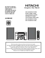
AXM628E
Brand: Hitachi Pages: 33
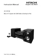
AX-M136i
Brand: Hitachi Pages: 25


