Sailrite ULTRAFEED LS, Manual Book
The Sailrite ULTRAFEED LS is a high-performance sewing machine designed for heavy-duty projects. With its durable construction and precision stitching, this versatile machine is a must-have for any sewing enthusiast. Manual book available for free download at manualshive.com, providing step-by-step instructions and detailed information to optimize your sewing experience.
Share
Download


Reviews:
No comments
Related manuals for ULTRAFEED LS

CHARGER 2022 ABLT
Brand: NSS Pages: 16

Me4
Brand: MDG Pages: 2

EXPANDER 750 PROPANO
Brand: KLINDEX Pages: 60

RE 98
Brand: Stihl Pages: 132

TFHX Series
Brand: TAJIMA Pages: 140
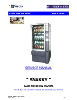
Snakky 6-27R/F
Brand: Necta Pages: 23

Cover Stitch Wide
Brand: Singer Pages: 13

109 LIPS
Brand: Mybelle Pages: 4

d-Copia 5002MF
Brand: Olivetti Pages: 269

Iris 10
Brand: Texi Pages: 34

PUNCH-BIND
Brand: JBI Pages: 36

CombBind DB28Pro
Brand: GBC Pages: 22
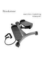
aerobic twisting stepper
Brand: Brookstone Pages: 14

AquaRide BRX 700
Brand: Nilfisk-Advance Pages: 82

Stilist Serger
Brand: Singer Pages: 2

2802
Brand: Singer Pages: 48

AMS-224EN4530R
Brand: JUKI Pages: 116

DLU-5494N-7
Brand: JUKI Pages: 4


