Safety Track UCIT BASIC 2, Installation Manual
The Safety Track UCIT BASIC 2 Installation Manual is available for free download on our website. This comprehensive manual provides step-by-step instructions for setting up and using the product. Ensure optimal safety and functionality by accessing the manual at manualshive.com.
Share
Download


Reviews:
No comments
Related manuals for UCIT BASIC 2

QooCam 8K
Brand: KanDao Pages: 49

Lumix DMC-FT25
Brand: Panasonic Pages: 24
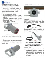
EXPCMR-ALG-OZ-IC-1080P-1224 HD-TVI
Brand: Larson Electronics Pages: 4

JK-309
Brand: Delta Pages: 2

DiMAGE G500
Brand: Konica Minolta Pages: 126

NAVSPORTMINI
Brand: Navig8r Pages: 11
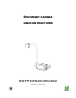
AVER F17
Brand: ICTS Pages: 6

OM-5
Brand: OM SYSTEM Pages: 467

F004
Brand: Tamron Pages: 2

5345z
Brand: Concord Camera Pages: 61

BVS SC Series
Brand: Balluff Pages: 45

C11440-10C
Brand: Hamamatsu Photonics Pages: 38

QV-4000
Brand: Casio Pages: 53

Zoom Mini
Brand: FlashPoint Pages: 20

SKYE WiFi 3
Brand: Accu-Scope Pages: 19

GL-H02
Brand: Greenleaf Pages: 4

SNC-521IR/W
Brand: Santec Pages: 40

JC600
Brand: Jimi Pages: 12


