


Reviews:
No comments
Related manuals for BP 56

TOYBOX
Brand: UNIS Pages: 19

Astro
Brand: Necta Pages: 13
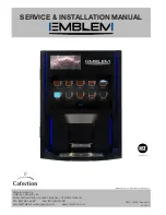
EMBLEM
Brand: Cafection Pages: 82

Colibri
Brand: Necta Pages: 48
Colibri
Brand: N&W Global Vending Pages: 23

186
Brand: Vendors Exchange Pages: 13

Easy 6000
Brand: Westomatic Pages: 41

Triple Crown
Brand: A&A Global Industries Pages: 16
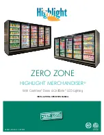
Highlight MERCHANDISER 1RHCC30
Brand: Zero Zone Pages: 53
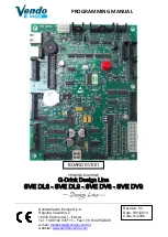
SVE DL6
Brand: Vendo Pages: 48

VC6000
Brand: Seaga Pages: 13

SINFONIA GF6
Brand: Necta Pages: 44
Snakky 6-27R/F
Brand: Necta Pages: 23
KLIX Series
Brand: LAVAZZA Pages: 32
SIID
Brand: Dixie Narco Pages: 14
RVV 700
Brand: Royal Vendors Pages: 76

BOX MONETIERA
Brand: Saeco Pages: 32
Argenta
Brand: Azkoyen Pages: 88


