background image

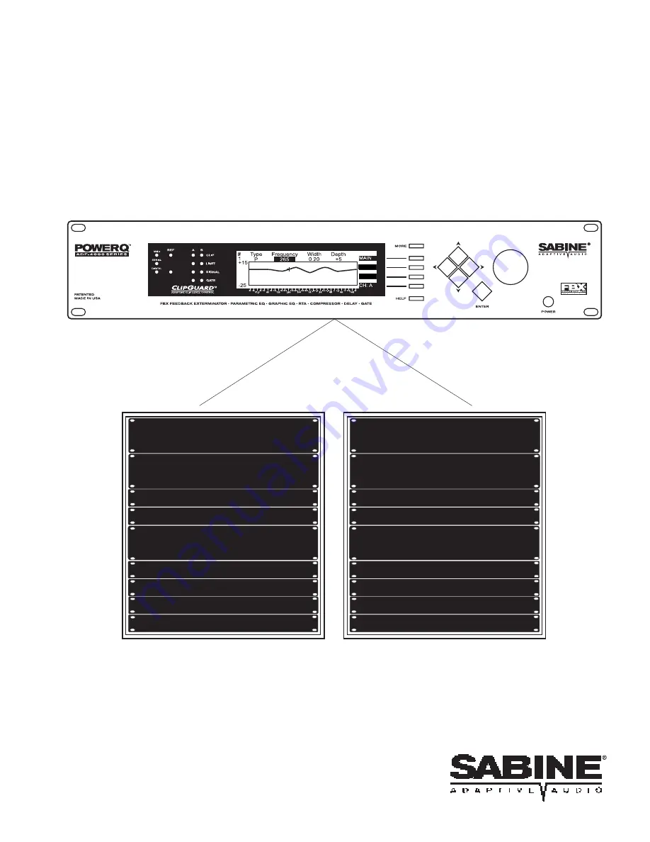
The two-channel POWER-Q gives you

two full racks of gear -- all in one!

Automatic Room Flattening EQ

Program Shaping EQ

FBX Feedback Exterminator

Parametric EQ

Digital Delay

Downward Expander/Gate

Program Memory

Real-Time Analyzer

Compressor/Limiter

Digital Delay

Automatic Room Flattening EQ

Program Shaping EQ

FBX Feedback Exterminator

Parametric EQ

Digital Delay

Downward Expander/Gate

Program Memory

Real-Time Analyzer

Compressor/Limiter

Digital Delay

CURVE

TURB -

Summary of Contents for Power-Q

Page 1: ...xterminator Parametric EQ Digital Delay Downward Expander Gate Program Memory Real Time Analyzer Compressor Limiter Digital Delay Automatic Room Flattening EQ Program Shaping EQ FBX Feedback Exterminator Parametric EQ Digital Delay Downward Expander Gate Program Memory Real Time Analyzer Compressor Limiter Digital Delay CURVE TURB ...

Page 2: ... Q Digital Delay 14 8 1 Digital delay applications and use 8 2 POWER Q digital delay adjustments Manual and automatic 9 0 Using the POWER Q Automatic Room EQ 23 9 1 What is Automatic Room EQ 9 2 How Automatic Room EQ works 9 3 Reference microphone choice 9 4 Reference microphone placement 9 5 POWER Q controls for Automatic Room EQ 10 0 Using the POWER Q Graphic Equalizer 29 10 1 Graphic equalizer ...

Page 3: ... Program EQ 16 3 Using the POWER Q stored configuration window 17 0 Global Parameters Configuring Internal Default Values 48 18 0 Password 50 19 0 POWER Q Options 51 20 0 Remote Control of the POWER Q 51 20 1 Computer Requirements 20 2 Installing SABINE POWER Q Remote Software 20 3 Using SABINE POWER Q Remote Software 20 4 POWER Q Remote Software Guide 21 0 POWER Q Digital I O Option 60 22 0 Bypas...

Page 4: ...nel fully adjustable compressor limiter Full featured filter based RTA 2 channel digital delay for programmable time alignment of speakers by up to 83 2 mSec 99 memory settings Instant recall of all or selected parameters Automatic Room EQ Calibrate a system in any acoustic space to a flat response curve automatically in just a few seconds ClipGuard Adaptive Clip Level Control This patented Sabine...

Page 5: ...LP screen is activated HELP will appear in lower right of display window To escape HELP screen press HELP button again Soft Key Selectors SERIAL REMOTE OPTION DA I O OPTION Channel B Input and Output XLR 3 Channel A Input and Output XLR 3 Reference Mic Input XLR 3 IEC 320 C14 AC Power Connector Ground Lift Switch Differing ground potentials between or among interconnected equipment racks may intro...

Page 6: ...6 Sections 2 3 Menus Diagrams Fig 4 POWER Q Internal Signal Path 2 1 MAIN MENU WINDOWS QUICK REFERENCE Section 3 Block Diagram Internal Signal Path Fig 3 Main Menu Items ...

Page 7: ...d the monitor output into Channel B Then plug Channel A POWER Q output into your main power amp and Channel B POWER Q output into your monitor power amp This will allow use of the POWER Q as if it were two sepa rate mono units The configuration looks like this The POWER Q may also be used at a mixer insert point either for a single input channel or for a group or bus insert point This will dedicat...

Page 8: ... amplifier into any POWER Q input This will VOID your warranty 4 2 BYPASSING THE POWER Q The POWER Q allows flexible options for bypassing all or part of its internal processing For more details please refer to Section 22 A quick bypass can be accomplished simply by turning the unit off which routes the input jack directly to the output However please note two cautions when turning the POWER Q on ...

Page 9: ...and low pass filter are available for each channel These filters are accessed using the up down arrow keys and can be set to parametric PARAM using the data wheel The data wheel and left right arrows set the frequencies filter widths and filter depths of all filters Any changes made to the parametric filters will add to the overall EQ of the system including graphic EQ settings 5 2 EXTERMINATING F...

Page 10: ...e extremes of speaker cone flexion All of these functions are designed to maximize your gain without distortion Maximizing gain would be a far simpler matter if it weren t for the problem created by adding gain to a microphone in the presence of a speaker which in turn reproduces the mic s sound with the mic in turn amplifying its own input and so on At some point at least one frequency will regen...

Page 11: ...in real time If you d rather use your time to set up mics patch in the rest of your gear or take a break the POWER Q Automatic Room EQ feature will analyze the room for you and optimize your system EQ to the response curve you specify At the next venue you can do a quick room analysis in less than a minute then you can recall the memory of all your other EQ settings and every other parameter previ...

Page 12: ...ith careful speaker and microphone placement To go beyond the limitations inherent in a less than desirable acous tical space you ll have to call in the artillery electronics and equalization to optimize your sound system This is why a device like the POWER Q is worth every cent and then some of its very reasonable price 7 2 STEP TWO TIME ALIGNMENT OF SPEAKERS Compared to light or electronic signa...

Page 13: ... make adjustments 7 4 STEP FOUR TWEAKING THE EQ Once the room is flat you may want to customize the room equalization to meet your own personal tastes or to match the entertainers performance style You may do this either by making further adjustments with a second graphic equalizer see Section 10 or by inserting up to 12 parametric filters per channel for very precise adjustment see Section 11 The...

Page 14: ...here are several powerful tools available for precisely measuring the time a loudspeaker signal takes to arrive at a certain point in the audience Most of these tools are very sophisticated and tend to be quite expensive Fortunately simpler tools are sufficient for most applications In the 1930 s engineers synchronized the low and high frequency speakers in movie theaters by feeding a sharp click ...

Page 15: ...ated from two separate point sources The waves from each source combine to form visible interference patterns In some places the wave crests and troughs are in phase so they combined to make a larger wave In other places the crests are out of phase so the crest of one wave source is canceled by the trough of the other Ripple tank experiments show the interference patterns are strongest when the am...

Page 16: ...uencies increase in amplitude by 6 dB while the out of phase frequencies cancel completely to 4 dB Comb filters cause a lot of problems The frequencies that are reinforced are prone to excite feedback while the out of phase cancellations make the program sound thin and over equalized Try this simple experiment to hear what comb filters do to your sound Section 8 Digital Delay 16 Fig 9 COMB FILTERS...

Page 17: ...program was played through both speakers simultaneously the listener perceived the acoustic image the direction from which the sound seemed to be coming centered between the speakers When Haas delayed the signal going to one of the speakers by somewhere between 5 to 35 milliseconds the listener perceived a shift in the acoustic image to the speaker heard first While the delayed speaker did not con...

Page 18: ...alcony speaker are equal See Comb Filter Distortion p 15 You can use the POWER Q to precisely synchronize the speakers along this axis to eliminate the most severe comb filters Comb filters off the equal level axis are much less of a problem since a louder signal is not affected very much by a weaker signal Finally you can experiment with adding 5 to 10 milliseconds delay to both sets of speakers ...

Page 19: ...e second performer by placing the POWER Q in the mixer s channel insert point and adding a 25 msec delay Certainly taking advantage of the Precedence Effect is not as obvious to the audience as eliminat ing feedback but it is nice to know you did all that is possible to make the performance enjoyable Application III Synchronizing the signals of a far throw and short throw loudspeaker In order to r...

Page 20: ... is 1 38 milliseconds per channel the maximum is 83 2 milliseconds Note that manually adjusting the digital delay during audio program may cause discontinuities popping sounds while the adjustments are made This is unavoidable and will cease when the delay is set Delay times may also be set manually from inside the POWER Q REAL TIME ANALYZER window Refer to Section 13 3 for more details Automatic ...

Page 21: ...o align speakers if you are only operating with one channel of the POWER Q and the unit will not allow you to test only one channel when there is no signal present at one of its inputs Check your connections and signal path and repeat the procedure If the POWER Q detects the presence of a signal at its two inputs it will automatically play a 1 Khz test signal first to calibrate the sensitivity of ...

Page 22: ...ow will appear When the microphone hears the signal the POWER Q will time how long the signal takes to reach the microphone from each channel s output and adjust the delay times to make the signals arrive after the same length of time subject to the 83 2 millisecond maximum value The POWER Q will revert to displaying the DIGITAL DELAY screen however each speaker s output delay and the distance fro...

Page 23: ...lated by the POWER Q on the basis of measurement of acoustic energy heard at a reference microphone and designed to provide a neutral repeat able starting point for additional program equalization and signal processing The EQ curve calculated is designed to make the response curve heard at the microphone as flat as possible compensating for room acoustics and the frequency response of the sound sy...

Page 24: ...e microphone as shown below This orientation is more likely to produce accurate frequency response measurement in the same direc tional orientation as the ears of the listener i e parallel to the floor and perpendicular to the apparent direction of the microphone s pointing In most circumstances a free field microphone is the best choice for room analysis However in some instances a cardioid mic m...

Page 25: ...rriving from multiple point sources will arrive at the microphone at different times When running a stereo source through a stereo sound system the POWER Q will automatically analyze one channel at a time in sequence But again multiple speakers in the sound path of either channel should be selectively disconnected so only one speaker plays sound during the analysis NOTE Make sure you plug only a m...

Page 26: ...ulates the appropriate roll off depending on the speaker to mic distance To summarize selecting COMPENSATE will cause the Automatic Room EQ analysis to produce a response curve with more high frequency information at distances closer to the speak ers In small rooms this compensation may not be necessary To implement simply highlight your choice to compensate or not Now play your test audio through...

Page 27: ...ay not permit the microphone to hear the 1kHz tone due to phase cancellation In rare instances e g extremely loud conditions it s possible that the signal heard at the reference mic input might be too hot which will produce an alternative error message You may need to put a pad on the microphone or at the POWER Q input via Global Parameters Alter natively try placing the microphone a further dista...

Page 28: ...n 6 dB boost to any EQ slider Also note that the Graphic EQ screen on the POWER Q will NOT show any boost or cut of sliders after the Automatic Room EQ function is completed The Auto Room EQ settings are shown only as a superimposed response curve leaving the EQ sliders free for you to make additional changes to the EQ what we call Program EQ The total EQ and filtering added by the POWER Q will pr...

Page 29: ...raphic EQs The first EQ is automatically set by the POWER Q using the Automatic Room EQ function see Section 9 Its function is to make the frequency response of the acoustical environment as even as possible or flat We call this response curve the Room EQ Although the POWER Q makes graphic EQ adjustments to produce the Room EQ the actual slider settings for these adjustments are NOT displayed inst...

Page 30: ...oft key 2 GRAPHIC EQ from the MAIN MENU The MAIN MENU options can be scrolled using the MORE button or up down arrow keys Pushing this key will display the image of a 31 band graphic equalizer on the screen The frequency midpoints of each band are displayed at the bottom of the equalizer window There are two pages to the GRAPHIC EQ controls accessed by pressing the MORE button Press ing MORE chang...

Page 31: ...ic EQ screen see Section 11 3 Curve Display and Bypass The curve displayed combines all the EQ and filtering active in the POWER Q signal path If either the Program EQ or Room EQ is bypassed or if both are bypassed as described in Section 22 the curve display will reflect the bypass Reset The RESET button soft key 2 opens up a screen that will allow global resetting of all filters for both channel...

Page 32: ...anges changes in gain musicians almost always play louder during a performance than at sound check and changes in mic position e g with a wireless mic often result in new feedback frequencies arising during performance When a new feedback frequency occurs a new DYNAMIC FBX filter is automatically assigned to eliminate the feedback When all of the DYNAMIC filters have been used the filter that was ...

Page 33: ...methods use these ONLY for setup of identifying and eliminating feedback frequencies For any of the modes you must have your sound system set up plugged in and all your microphones in place and turned on The three methods of setup are Normal default mode which involves simply configuring your FBX filters as you desire see Section 11 1 then slowly raising the master mixer output assuming the POWER ...

Page 34: ...fixed filters to prevent them from notching more deeply press the LOCK soft key at the right of the screen so it reads LOCK 7 Repeat this procedure for the other channel Auto Turbo Setup notes With Auto Turbo Setup follow these steps 1 3 Follow steps 1 3 of normal FBX setup 4 Press the Turb soft key to open up the Turbo screen 5 Highlight Auto Turbo setup using the arrow keys 6 Bringing your syste...

Page 35: ...rbo mode is somehow left on when the FBX setup procedure is completed or ended prematurely you may experience distorted audio through the POWER Q since the clip level will be turned up fully and easily overloaded by input level This problem is easily remedied by turning Turbo mode off Turbo mode will NOT affect the output level of the POWER Q NOTE The Turb soft key will be ghosted after setup is c...

Page 36: ...espond to the settings in LIST mode The filter chosen for this top line can be changed using the up down arrow keys NOTE This is important as all other parameters are adjusted using the data wheel after selecting parameters with the left right arrow keys When the displayed filter is set to PARAM using the data wheel the frequency width and depth of the parametric filter can be changed by using the...

Page 37: ...filters in the Graphic EQ window see section 10 2 The LOCK soft key locks and unlocks fixed FBX filters A locked FBX filter will not change or notch any deeper 11 6 PREVENTING FEEDBACK IN THE EVENT OF EQUIPMENT FAILURE If you re concerned about the potential feedback problems that may arise in the very unlikely event of a POWER Q failure during a performance you can relieve your concerns by progra...

Page 38: ...ow pass filter The HIGH PASS FILTER can be used to suppress phenomena such as low frequency rumble while the LOW PASS FILTER can be used for attenuating high frequency hiss or for band limiting the POWER Q s output signal for telecommunications This screen allows setting of the high and low pass filter points The HIGH PASS FILTER can be inserted starting at any frequency up to 3 000 Hz The LOW PAS...

Page 39: ...sponse may disappear from the screen because it is below the range being displayed You may move the range displayed on the screen with the up down arrow keys to bring the RTA response into optimal view When the up down arrow keys are enabled to perform this function an up down arrow icon will appear at the left extreme of the screen display Pressing the third soft key NOISE accesses the NOISE GENE...

Page 40: ...antom soft keys that only appear when you select an option in the noise generation options window Pressing NOIS increases noise level and pressing NOIS decreases noise level Press MORE again to see this screen 40 Section 13 RTA P H 0 1 4 4 Adjusts the peak and hold reset time of the RTA from instantaneous P H 0 to 1 second 4 seconds or the highest peak 4 WT NO A B C Choose among A B or C weighting...

Page 41: ...s at equal volume From the MAIN MENU select option 4 REAL TIME ANALYZER Select REF at soft key 4 this will display the RTA response of the reference microphone Then press the MORE button 3 times to reveal the screen in Fig 48 on page 40 of this manual Press soft key 3 NOISE The NOISE GENERATION OPTIONS screen Fig 45 page 39 will appear Set the gain of the noise generator to the desired setting the...

Page 42: ...mon negative side effect of compression is a pumping or breathing sound that sometimes accompanies constant gain modulation This can be minimized by proper adjustment of the attack release thresh and knee controls 14 2 POWER Q COMPRESSOR LIMITER ADJUSTMENTS The POWER Q compressor limiter menu is accessed from the MAIN MENU by pressing soft key 5 COMPRESSOR LIMITER OUTPUT allows you to vary the sig...

Page 43: ...compressed so extremely as to reflect no additional gain at the output stage Note that the LIMIT threshold and the compressor threshold THRESH can be set independently allowing both a mild degree of compression and brick wall peak limiting All other parameters besides THRESH and RATIO are common for both the compressor and limiter ATTACK sets the speed with which the signal is compressed once the ...

Page 44: ...between a mixer and an amplifier where you run the risk of abruptly turning off low level portions of your mix via poor gate settings 15 2 POWER Q EXPANDER NOISE GATE ADJUSTMENTS The POWER Q expander gate is accessed by pressing soft key 6 from the MAIN MENU EXPANDER NOISE GATE The window looks like this Many of the EXPANDER NOISE GATE parameters are essentially identical to COMPRESSOR LIMITER adj...

Page 45: ... return to unity gain when the input level threshold is crossed It is adjustable from 1 to 99 milliseconds with 1 millisecond resolution RELEASE sets the speed of the expansion onset and is adjustable from 50 milliseconds to 5 seconds The expander gate functions are separately adjustable for channels A and B When expansion or gating is engaged i e when the threshold is crossed for a low KNEE value...

Page 46: ...d by the user 16 3 USING THE POWER Q STORED CONFIGURATION WINDOW Select option 8 STORED CONFIGU RATIONS from the MAIN MENU soft keys to access these controls There are 100 memory locations for loading and 99 for storing user presets accessible by scroll ing with the up and down arrow keys These are numbered consecutively followed by a memory name user definable and a suffix The suffix CRV indicate...

Page 47: ...e only or all parameters except Program Shaping Curve assuming you saved all the parameters when you originally created the memory Otherwise your load options will be limited to the parameters you saved Hit ENTER to load your selection Note that loading new parameters with or without the Program Curve will briefly mute audio that is playing through the POWER Q when LOAD is executed This will preve...

Page 48: ...WER Q to over 110 dB We highly recommend leaving the CLIP ADJUST control set to CLIPGUARD EQ FILTER WIDTH sets the width of the graphic EQ filters as defined by the width of a filter notch at the 3dB half power level Note that the graphic EQ filters are constant Q filters mean ing their width will not change as the filter depth increases EQ FILTER WIDTH is adjustable from 5 to 1 0 octave in 01 oct...

Page 49: ...low harmonic content and can be easily mistaken for feedback by the POWER Q Higher values of SENSITIVITY will allow feedback to grow larger in magnitude before it is detected and eliminated too low a value can result in mistaking certain musical tones for feedback Use the DEFAULT setting of 5 for most venues use the value 2 for more classical venues and 4 for spoken word applications Range of valu...

Page 50: ...ill remember your password and return to MAIN MENU You may then proceed with normal POWER Q opera tion When the POWER Q is switched off and turned back on the following window will appear To enter your password turn the data wheel clockwise The five digit code 10000 will appear and you must enter your password using the left right arrow keys and data wheel When you have scrolled to the correct pas...

Page 51: ... 5 SVGA or greater resolution graphic card and monitor 6 One COMM port for a serial connection with a 16550 or faster comm chip 7 Cables Connector If your computer has a 9 pin COMM port use a standard 9 pin male to 9 pin female RS232 standard computer store connectors for example Radio Shack Cat No 26 117 Plug into the POWER Q s back panel RS232 male jack labeled SERIAL If you computer s COMM port...

Page 52: ...the tool bar at the top of the screen for a list of all the features available via remote control You can also use the feature icons or the Function keys to select various POWER Q features 5 You may regain front panel control of any POWER Q in the system by entering the password with the data wheel and arrow keys The remote software disconnects all units in the chain whenever front panel control i...

Page 53: ...re functions without an actual connection to a Power Q POWER Q SETUP SCREEN The SETUP SCREEN appears when the program is opened and presents the following four options Section 20 Remote Control Select COMM Port Permits selection of COMM Ports available on your system Network Chain Screen Clicking Connect POWER Qs will prompt the computer to search along its serial network connection for any POWER ...

Page 54: ...nel display on the POWER Q unit itself Section 20 Remote Control Main RTA Screen Upper Icon Bar The icons across the top of the screen represent the functions of the Power Q These functions can be selected by one of three methods a mouse click on the icon click and release pull down from the Main Menu or by pressing the Function keys of your computer keyboard As indicated in the pull down menu F1 ...

Page 55: ... curve will be displayed with the proper channel color scheme at the top of the graphic EQ screen Curve view selections EQ type This will control the EQ contributing to the total EQ curve displayed at the top of the graphic EQ screen Choose among Program EQ Room EQ or both Note that the display of the curve will NOT affect the EQ active in the box unlike Bypass which will affect the audio signal a...

Page 56: ...k time release time Expander threshold ratio knee Noise gate threshold attack time release time Output level Graphic EQ boost cut filter width Bypass Phantom power High and low pass filters FBX Filter width max depth tracking persistence sensitivity Delay Settings 20 dB reference microphone roll off Serial Connections If there is more than a single POWER Q connected to the network these boxes repr...

Page 57: ...ination as indicated by a solid line and arrow connecting the source and each selected POWER Q a second click disarms copy and removes the connecting line Select All Stations will arm the copy function for all POWER Qs in the Copy To column Clicking any or all POWER Qs in the right hand column prepares the copy network Section 20 Remote Control 57 Pull Down Menus Main Menu pull downs Figure 69 all...

Page 58: ...antom power 20 dB reference microphone roll off High and low pass filters 31 Band Graphic EQ boost cut 12 FBX Parametric filters type frequency depth width 1 COPY ALL PARAMETERS 31 Band EQ High Low pass Filter When selected the functions below are copied Delay Settings Compressor threshold ratio knee Limiter threshold attack time release time Expander threshold ratio knee Noise gate threshold atta...

Page 59: ...s AUTOMATIC ROOM EQ To insure quick and accurate communication between POWER Q units and your computer make sure to turn off all audio signals feeding the inputs of POWER Q units NOT performing Automatic Room EQ analysis until the analysis is complete Perform Automatic Room EQ for single units only in sequence FBX Setup For similar reasons turn off all audio inputs to POWER Qs except the unit with...

Page 60: ...lipGuard function is automatically disabled so only the output level of the unit will be adjust able when using the controls found in the GLOBAL PARAMETERS screen Sample rate of the POWER Q output is adjustable using the arrow keys and data wheel Select able samples rates include 32 KHz 44 1 KHz 48 KHz or a match to the sample rate of the digital input source Regardless of the input chosen the POW...

Page 61: ...during Automatic Room EQ Program EQ represents the changes imposed by the user in addition to the Room EQ Program EQ only Room EQ only None No function or EQ in the POWER Q is bypassed all are active The placement of the X will indicate which bypass option is currently engaged The option with the X means the selected features are NOT in the audio signal path Make your choice by moving the X up and...

Page 62: ...without taking out a big chunk of music in the same slice I was introduced to the Sabine line of feedback eliminators a few years ago when I was working on Ann Margret s stage show with my friend John Reed He had found that the FBX 900 afforded him a good deal more gain before feedback on Ann Margret s mic than what he had been able to attain manually in the past And since she s a quiet singer thi...

Page 63: ...nd I want to cover that situation as well Besides experimenting with widening filters I also set an unused ADF filter to D for the show to catch feedback that may occur under performance conditions The beauty of the Sabine FBX filters is how well they detect feedback even when music is playing After I ve completed the ringing out process I ll try and use the ADF s integral delay and gate to furthe...

Page 64: ... the mixer input channel Or you may have used up all the available FBX filters leaving no additional filters for new feedback frequencies PROBLEM SUGGESTION Check connections Are input and output reversed Is the POWER Q LED showing signal If no make sure the unit is not in BYPASS mode and that audio signal is feeding POWER Q input If yes check connections and gain downstream from POWER Q Try using...

Page 65: ...05 to 5 sec in 05 sec steps Expander Noise Gate Threshold 20dBu to 90 0dBu in 0 5dB steps Ratio 1 1 1 4 2 3 4 5 6 7 8 9 10 16 32 infinite Knee 1 hardest to 40 softest Attack 1 to 99 msec in 1 msec steps Release 05 to 5 sec in 05 sec steps Digital Delay 1 38 83 28 milliseconds channel in 20 microsecond steps Automatic or User Programmable in feet or meters Password Configuration 5 numeric character...

Page 66: ...in on the power supply cord 10 Power supply cords should always be handled carefully Never walk or place equipment on power supply cords Periodically check cords for cuts or signs of stress espe cially at the plug and the point where the cord exits the unit 11 The power supply cord should be unplugged when the unit is to be unused for long periods of time 12 Care should be taken so that objects do...

Page 67: ...AVINGS ANY INCIDENTAL DAMAGES OR ANY CONSEQUENTIAL DAMAGES ARISING OUT OF THE USE OR INABILITY TO USE THE PRODUCT EVEN IF SABINE HAS BEEN ADVISED OF THE POSSIBILITY OF SUCH DAMAGES THESE LIMITED WARRANTIES ARE IN LIEU OF ANY AND ALL WARRANTIES EXPRESS OR IMPLIED INCLUDING BUT NOT LIMITED TO THE IMPLIED WARRANTIES OF MERCHANTABILITY AND FITNESS FOR A PARTICULAR USE PROVIDED HOWEVER THAT IF THE OTHE...

Reviews: