Sabik Marine carmanah 800 Series, Руководство пользователя
Приобретите свою улучшенную модель Сабик Марин Карман 800 Series и получите бесплатное руководство пользователя! Скачайте руководство с manualshive.com и начните наслаждаться всеми функциями этого высококачественного продукта. Не упустите возможность ознакомиться с руководством перед использованием устройства.
Поделиться
Скачать


Отзывы:
Нет отзывов
Похожие инструкции для carmanah 800 Series

IC-M80
Бренд: Icom Страницы: 27
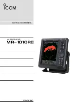
MR-1010RII
Бренд: Icom Страницы: 72

Dual
Бренд: IDS Страницы: 2

632681
Бренд: Homebase Страницы: 2

43064
Бренд: SHOWTEC Страницы: 21

T-Flow Tronic Series
Бренд: velda Страницы: 8

LIGHTLINE PC972
Бренд: BROKIS Страницы: 2
67515
Бренд: Astral Pool Страницы: 20

Forza 60B II
Бренд: NANLITE Страницы: 36

ML-4030 LED
Бренд: DÖRR Страницы: 16

35710
Бренд: MAXLOAD Страницы: 4

Flar
Бренд: Lodes Страницы: 12

CLAYMORE ULTRA mini
Бренд: Prism Страницы: 2

SpectralLED RS-7
Бренд: gamma scientific Страницы: 81

MCB 7270
Бренд: Navman Страницы: 18

PVP S5
Бренд: Chauvet Professional Страницы: 112

M20H-HEDRA L DIM5
Бренд: deltalight Страницы: 3

XR 5 WASH
Бренд: DTS Страницы: 24


