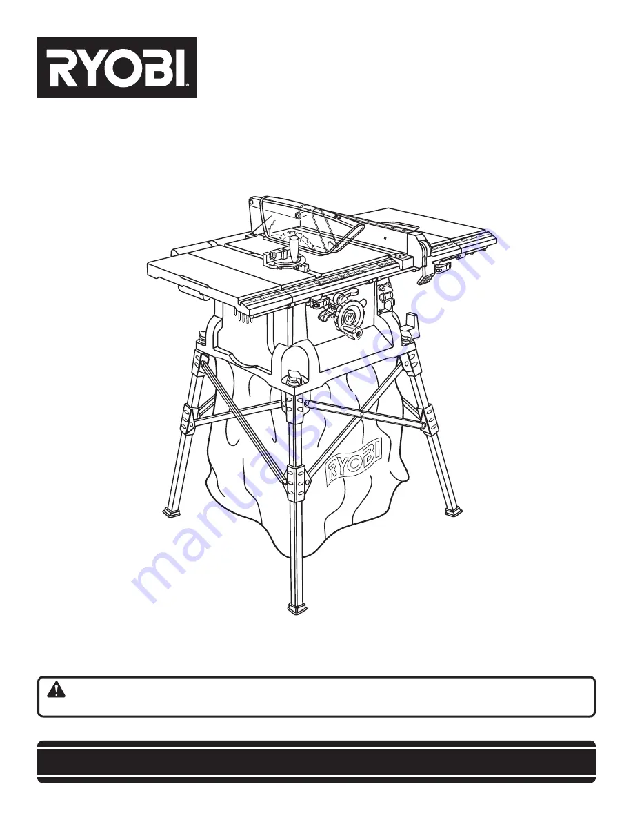
background image

OPERATOR’S MANUAL

10 in. TAbLE SAw

bTS16

SAVE THIS MANUAL FOR FUTURE REFERENCE

You

r table saw h

as been engineered and manufactured to our high standard for dependability, ease of operation, and  

operator safety. When properly cared for, it will give you years of rugged, trouble-free performance.

wARNING:


To reduce the risk of injury, the user must read and understand the operator's manual before using  

this product.

Thank you for your purchase.

Summary of Contents for BTS16

Page 1: ...manufactured to our high standard for dependability ease of operation and operator safety When properly cared for it will give you years of rugged trouble free performance WARNING To reduce the risk of injury the user must read and understand the operator s manual before using this product Thank you for your purchase ...

Page 2: ...nety 90 days Batteries are warranted for two years HOW TO GET SERVICE Just return the power tool properly packaged and postage prepaid to an Authorized Service Center You can obtain the location of the Service Center nearest you by contacting a service representative at One World Technologies Inc P O Box 1207 Anderson SC 29622 1207 by calling 1 800 525 2579 or by logging on to www ryobitools com W...

Page 3: ...Y GLASSES WITH SIDE SHIELDS Everyday eyeglasses have only impact resistant lenses they are not safety glasses SECURE WORK Use clamps or a vise to hold work when practical It s safer than using your hand and frees both hands to operate tool DON T OVERREACH Keep proper footing and balance at all times MAINTAIN TOOLS WITH CARE Keep tools sharp andcleanforbetterandsaferperformance Followinstruc tions ...

Page 4: ... saw Failure to do so can result in an accident causing possible serious personal injury ALWAYS USE BLADE GUARD Spreader AND ANTI KICKBACK PAWLS on all through sawing use brake fluids gasoline petroleum based products or any solvents to clean tool STAY ALERT AND EXERCISE CONTROL Watch what you are doing and use common sense Do not operate tool when you are tired Do not rush DO NOT USE TOOL IF SWIT...

Page 5: ... hand to move into the cutting tool Use only recommended accessories listed in this manual or addendums Use of accessories that are not listed may cause the risk of personal injury Instruc tions for safe use of accessories are included with the accessory make sure the work area has ample lighting to see the work and that no obstructions will interfere with safe operation BEFORE performing any work...

Page 6: ...speed orbits etc per minute Do not expose to rain or use in damp locations To reduce the risk of injury user must read and understand opera tor s manual before using this product Eye Protection Precautions that involve your safety Failure to keep your hands away from the blade will result in serious personal injury Wet Conditions Alert min Per Minute Class II Construction no No Load Speed Direct C...

Page 7: ...he product to the nearest AUTHORIZED SERVICE CENTER for repair When servic ing use only identical replacement parts WARNING To avoid serious personal injury do not attempt to use this product until you read thoroughly and understand com pletely the operator s manual If you do not understand the warnings and instructions in the operator s manual do not use this product Call Ryobi customer service f...

Page 8: ... drop will cause a loss of power and the motor will overheat If the saw does not operate when plugged into an outlet double check the power supply ELECTRICAL SPEED AND WIRING The no load speed of this tool is approximately 5 000 RPM This speed is not constant and decreases under a load or with lower voltage For voltage the wiring in a shop is as important as the motor s horsepower rating A line in...

Page 9: ...g dropped into the blade or being placed inadvertently in contact with the blade Workpiece or Material The item on which the operation is being done Worktable Surface where the workpiece rests while performing a cutting drilling planing or sanding operation Anti Kickback Pawls radial arm and table saws A devise which when properly installed and maintained is designed to stop the workpiece from bei...

Page 10: ... V AC only 60 Hz Input 15 Amps No Load Speed 5 000 r min RPM Cutting Depth at 0 3 in Cutting Depth at 45 2 1 2 in MITER gauge BLADE GUARD STORAGE BRACKET S FRONT RAIL LOCKING LEver SWITCH SCALE HEIGHT bevel ADJUSTING HANDWHEEL BEVEL LOCKING LEVER BEVEL SCALE BEVEL INDICATOR RIP FENCE sliding table extension outfeed support sliding table extension table locking lever spreader ...

Page 11: ...ATURES HEIGHT BEVEL ADJUSTING HANDWHEEL Located on the front of the cabinet use this handwheel to lower and raise the blade for height adjustments or blade replace ment This handwheel also makes the adjustment for bevel angles easy MITER GAUGE The miter gauge aligns the wood for a cross cut The easy to read indicator shows the exact angle for a miter cut with positive stops at 90 and 45 MITER GAUG...

Page 12: ...ade is set with a handwheel on the front of the cabinet To accommodate wide panels the saw table has rails on each side Detailed instructions are provided in the Operation section of this manual for the basic cuts cross cuts miter cuts bevel cuts and compound cuts The rip fence is used to position work for lengthwise cuts A scale on the front rail shows the distance between the rip fence and the b...

Page 13: ...e provided with your saw Additional blade styles of the same high quality are available for specific operations such as ripping Your local dealer can provide you with complete information WARNING Do not use blades rated less than the speed of this tool Failure to heed this warning could result in personal injury Fig 4 Framing Square Phillips Screwdriver Flat Blade Screwdriver 1 2 in Wrench COMBINA...

Page 14: ...Spreader and Anti Kickback Pawls 1 B Miter Gauge 1 C Rip Fence 1 D Quick Stand leg stand 1 E Dust Bag 1 F Blade Wrench 2 G Hex Key 1 H Bevel Handle Assembly 1 I Extension Table left 1 J Extension Table right 1 K Indicator left 1 L Indicator right 1 M End Plug right 1 N End Plug left 1 O Screw M4 x 10 mm 2 P Screw M4 x 25 mm 2 ...

Page 15: ...is tool Any such alteration or modification is misuse and could result in a hazardous condition leading to possible serious personal injury WARNING Do not connect to power supply until assembly is com plete Failure to comply could result in accidental starting and possible serious personal injury WARNING Do not lift the saw without help Hold it close to your body Keep your knees bent and lift with...

Page 16: ...ement can occur during use If any tipping slid ing or walking is noted secure the workbench to the floor before operating To install BEVEL HANDLE See Figure 9 Hold the nylon nut securely and turn the screw counter clockwise to remove the nut completely NOTE Do not remove the screw from the handle or the washer from the end of the screw Place the nylon nut into the recessed hole on the back of the ...

Page 17: ... end into the flats on the arbor shaft Insert the closed end of the larger blade wrench over the hex nut Holding both wrenches firmly push the larger wrench to the back of the machine Make sure the blade nut is securely tightened Do not overtighten NOTE Arbor shaft has right hand threads Reinstall the throat plate Check all clearances for free blade rotation In cutting opera tions the scale will b...

Page 18: ... to align the spreader with the saw blade Once properly aligned securely retighten the wing nut to assemble the sliding extension tables See Figures 15 16 The rear extension rods are longer than the front extension rods and must be inserted into the plastic brackets under the saw table first Locate the left sliding extension table and slide the extension rods into the plastic brackets under the sa...

Page 19: ...achments or accessories not recommended can result in serious personal injury WARNING Although many of the illustrations in this manual are shown with the blade guard removed for clarity do not operate the saw without the blade guard unless specifi cally instructed to do so Fig 16 2 SCREW INDICATOR l Insert the limit screw in the rear extension rod and tighten Open the extension table completely W...

Page 20: ...c Operation of the TABLE Saw The 3 prong plug must be plugged into a matching outlet that is properly installed and grounded according to all local codes and ordinances Improper connection of the equip ment can result in electric shock Do not modify the plug if it will not fit the outlet Have the correct outlet installed by a qualified electrician Refer to the Electrical section in this manual CAU...

Page 21: ...h stick with small pieces of wood and also to finish the cut when ripping a long narrow piece of wood to prevent your hands from getting close to the blade Bevel cuts are made with an angled blade Bevel cross cuts are across the wood grain and bevel rip cuts are with the grain The rip fence must always be on the right side of the blade for bevel rip cuts Compound or bevel miter cuts are made with ...

Page 22: ...in 8 in 10 in and 12 in Drill a 3 8 in hole at the 8 in 10 in and 12 in marks Prepare the saw for ripping as discussed on page 28 Set the rip fence to allow approximately a 1 4 in finger to be cut in the stock Feed the stock only to the mark previously made at 6 in Turn the saw Off and allow the blade to com pletely stop rotating before removing the stock Reset the rip fence and cut spaced rips in...

Page 23: ...l by pushing the bevel lock lever all the way to the right Adjust the bevel angle by pushing the wheel in toward the saw then turning it Turning the wheel counterclockwise increases the angle of the blade bringing it closer to 45 Turning it clockwise decreases the angle bringing the blade closer to 90 Tighten bevel control by pushing the bevel lock lever to the left To Adjust the Bevel indicator S...

Page 24: ... rail Push the locking lever down to automatically align and secure the fence Check for a smooth gliding action If adjustments are needed see To Check the Alignment of the Rip Fence to the Blade in the Adjustment section of this manual TO use the miter gauge See Figure 26 The miter gauge provides greater accuracy in angled cuts For very close tolerances test cuts are recommended There are two mite...

Page 25: ...er Repeat with the back lever Slide the table extension to the desired width NOTE Use the scale on the front rail when a specific width is desired Once the extension tables are set to the desired width relock the front and back locking levers by pushing the levers back towards the saw base to use THE OUTFEED SUPPORT See Figure 28 The outfeed support slides to give the operator additional support f...

Page 26: ...is square If the distances are different square the blade with the following steps Extend the extension table see page 25 Loosen adjusting bolts 1 and 3 NOTE The adjusting bolts are located above the height bevel adjusting handwheel and under the saw table in the front of the saw Turn adjusting bolt 2 left or right until the blade is square NOTE If the back of the blade was too far from the fram i...

Page 27: ...mended you make test cuts on scrap wood Remove the rip fence by lifting the locking handle Set the blade to the correct depth for the workpiece Set the miter gauge to 0 and tighten the lock knob Place a support the same height as saw table behind the saw for the cut work Add supports to the sides as needed To turn the saw ON lift the switch button To turn saw OFF press the switch button down NOTE ...

Page 28: ... of cut Use a push block or push stick to move the wood through the cut past the blade Never push a small piece of wood into the blade with your hand always use a push stick The use of push blocks push sticks and featherboards are necessary when making non through cuts When the cut is made turn the saw off Wait for the blade to come to a complete stop before removing the workpiece making a miter c...

Page 29: ...ng handwheel until the bevel indicator is at the desired angle Push the bevel locking lever securely to the left to lock the angle Set the blade to the correct depth for the workpiece Set the miter gauge to 90 and press the bevel locking lever towards the table to lock Place a support the same height as saw table behind the saw for the cut work Add supports to the sides as needed Turn the power sw...

Page 30: ...t Use a push block or push stick to move the wood through the cut past the blade Never push a small piece of wood into the blade with your hand always use a push stick The use of push blocks push sticks and featherboards are necessary when making non through cuts Once the blade has made contact with the workpiece use the hand closest to the rip fence to guide it Make sure the edge of the workpiece...

Page 31: ...e weight of a large panel WARNING Make sure the blade guard assembly is installed and working properly to avoid possible serious injury Place a support the same height as saw table behind the saw for the cut work Add supports to the sides as needed Turn the power switch to the ON position NOTE Make sure the wood does not touch the blade before you turn on the saw Let the blade build up to full spe...

Page 32: ...sure the wood does not touch the blade before you turn on the saw Let the blade build up to full speed before feeding the workpiece into the blade Position the workpiece flat on the table with the edge flush against the rip fence Stand to the side of the wood as it contacts the blade to reduce the chance of injury should kickback occur Never stand directly in the line of cut Use a push block or pu...

Page 33: ...to make sure it turns freely then lower the blade Turn the power switch to the ON position NOTE Make sure the wood does not touch the blade before you turn on the saw Let the blade build up to full speed before feeding the workpiece into the blade Position the workpiece flat on the table with the edge flush against the rip fence Stand to the side of the wood as it contacts the blade to reduce the ...

Page 34: ...er is securely pushed to the left Raise the saw blade to its full height by turning the height bevel adjusting handwheel clockwise Using the smaller hex wrench insert the flat open end into the flats on the arbor shaft Insert the closed end of the larger hex wrench over the hex nut Holding both wrenches firmly pull the larger wrench forward to the front of the machine Make sure the blade nut is se...

Page 35: ...ighten the adjustment bolt Turn the bevel handle until the bevel indicator points to zero If the bevel handle is turned as far as possible and doesn t indicate zero properly you may need to adjust the bevel indicator NOTE It will be necessary to remove the bevel handle to adjust the bevel indicator If the blade is not an exact 45 loosen the adjustment bolt and the bevel locking lever Turn the beve...

Page 36: ...oosen the knob adjust the rod and tighten the knob Adjust the 0 stop screw until it rests against the stop pin Adjust the plus and minus 45 stop screws using a 45 triangle and the steps above TO CHECK THE ALIGNMENT OF THE RIP FENCE TO THE BLADE See Figure 49 Unplug the saw Raise the locking lever to permit the rip fence to be moved Place a framing square beside the blade and move the rip fence up ...

Page 37: ... with plastic parts Chemicals can damage weaken or destroy plastic which may result in serious personal injury MAINTENANCE Periodically check all clamps nuts bolts and screws for tightness and condition Make sure the throat plate is in good condition and in position Check the blade guard assembly To maintain the table surfaces fence and rails periodi cally apply paste wax to them and buff to provi...

Page 38: ...lade is dull Blade is heeling Work is fed too fast Rip fence is misaligned Wood is warped Rip fence is misaligned Blade not properly sharpened or set Replace blade Replace blade Tighten all hardware Reposition on flat surface Adjust legs of optional stand Check saw blade installation Replace blade if necessary Remount the rip fence Clean and wax rails Adjust clamp screw counterclockwise Adjust cla...

Page 39: ...ccurate 90 or 45 cuts Height bevel adjusting hand wheel is hard to turn Saw does not start Blade makes poor cuts Blade does not lower when turning height bevel adjusting handwheel Motor labors in rip cut Positive stops inside cabinet need adjusting Bevel Cuts Miter gauge is misaligned Miter Cuts Gears or screw post inside cabinet are clogged with saw dust Motor cord or wall cord is not plugged in ...

Page 40: ...ly designed to filter out microscopic particles ONE WORLD TECHNOLOGIES INC 1428 Pearman Dairy Road Anderson SC 29625 Phone 1 800 525 2579 www ryobitools com BTS16 Parts and Service Prior to requesting service or purchasing replacement parts please obtain your model and serial number from the product data plate MODEL NUMBER SERIAL NUMBER How to obtain Replacement Parts Replacement parts can be purc...

Reviews: